


Po
w
24-p
8-pi
n
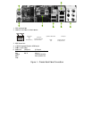
F
D
C
o
w
er Co
n
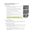
This moth
e
provide en
in ATX Po
w
PWR1
is t
h
DIMM slo
connector
make sure
n
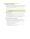
ATX 12V
P
PWR2
, th
e
the pins to
only fit in
o
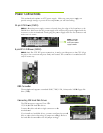
D
D Connec
t
T
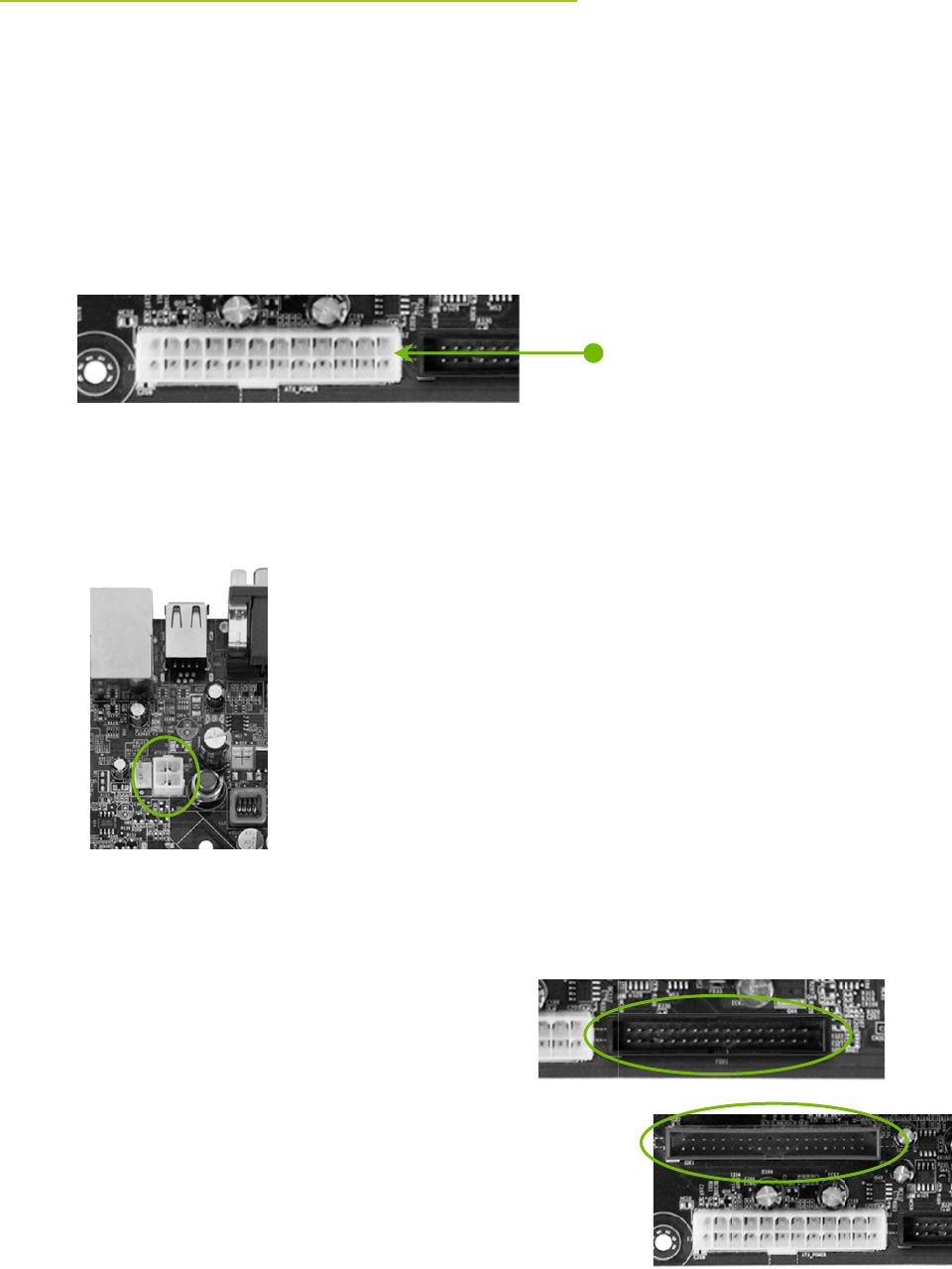
he moth
e
drive (FD
D
o
nnectin
g
I
T
he IDE
c
133/100/
6
Connect t
h
motherbo
a
If you inst
a
drive as a
s
the hard d
i
n
nectio
n
e
rboard requi
r
ough wattage
w
er (PWR1)
h
e main powe
ts. Make sure
on the moth
e
it is secure.
P
ower (PW
e
4-Pin ATX
1
the connect
o
o
ne way.
t
or
e
rboard supp
o
D
).
DE Hard D
i
c
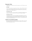
onnector sup
6
6 IDE hard
d
h
e cable end
w
a
rd.
a
ll two hard d
i
s
lave device b
y
i
sk document
a
n
s
r
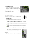
es an ATX p
to power all
t
r supply con
n
that the pow
e
e
rboard. Firm
l
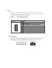
R2)
1
2V power co
n
o
r and press fi
r
o
rts a standar
d
i
sk Drives
ports Ultra A
T
d
isk drives.
w
ith a single c
o
i
sk drives, yo
u
y
setting its
j
u
a
tion for the
ju
ower supply.
t
he compone
n
n
ector located
e
r supply cabl
l
y plug the po
w
n
nection, is u
s
r
mly until sea
t
d
360K, 720
K
T
A
o
nnector to t
h
u
must config
u
mper accordi
n
u
mper settin
g
Make sure y
o
n
ts you will b
e
along the ed
g
e and pins ar
e
w
er supply ca
s
ed to provid
e
t
ed.
T
he con
n
K
, 1.2M, 1.44
m
h
e
u
re the secon
d
n
gly. Refer to
g
s.
o
ur power su
p
e
installing.
g
e of the boar
d
e
properly ali
g
ble into the c
o
e
power to th
e
n
ection is not
c
m
, and a 2.88
M
d
PWR1 connect
o
Plu
g
power cabl
from system po
w
supply to PWR1
p
ply can
d
next to the
g
ned with the
o
nnector and
e
CPU. Align
c
hed and will
M
floppy disk
o
r
e
w
er