


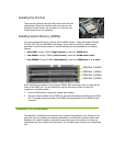
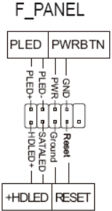
Front Panel Header (F_PANEL)
The front panel header on this motherboard is one connector used to connect the following four
cables.
PLED
Attach the front panel power LED
cable to these two pins of the connector. The Power LED indicates
the system’s status.
When the system is turned on, the LED is on. When the system is
turned off, the LED is off.
PWRBTN
Attach the power button cable from the case to these two pins.
Pressing the power button on the front panel turns the system on and
off rather than using the onboard button.
HDLED
Attach the hard disk drive indicator LED cable to these two pins. The
HDD indicator LED indicates the activity status of the hard disks.
RESET
Attach the Reset switch cable from the front panel of the case to
these two pins. The system restarts when
the RESET switch is pressed.
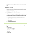
Expansion Slots
PCI Slots
The PCI slot supports many expansion cards such as a LAN card, USB card, SCSI card and
other cards that comply with PCI specifications. When installing a card into the PCI slot, be
sure that it is fully seated. Secure the card’s metal bracket to the chassis back panel with the
screw used to hold the blank cover.
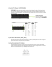
PCI Express x1 Slots
The PCI Express x1 slot is designed to accommodate PCIe x1 cards, such as an EVGA Killer
Xeno Network Card or Sound Card. The x1 slot provides 250 MB/sec bandwidth.
PCI Express x4 Slots
The PCI Express x4 slot is designed to accommodate PCIe x1/x4 cards.
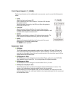
PCI Express x16/x8/x1 Slots
These PCI Express slots are reserved for Graphic Cards and PCI Express x1 devices. The
design of this motherboard supports multiple Graphic Card technology.
When installing a PCI Express Graphic Card, be sure the retention clip snaps and locks the
card into place. Secure the card’s metal bracket to the chassis back panel with the screw used
to hold the blank cover.