


2-3
USB HUB4 Series • Installation
PRELIMINARY
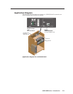
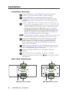
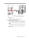
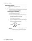
The rear panels of the USB HUB4 AAP and MAAP models contain two types of
USB In connectors, either of which can be used for the USB cable that connects your
computer to the HUB4.
a
Power connector — If using an Extron external 12 VDC power supply to
power the HUB4, connect it to the rst two pins (labeled In) of this 4-pole,
3.5 mm direct insertion captive screw connector. (See “Connecting to the
captive screw USB connector”, below)
If desired, connect another Extron wall mounted device (for example, an
MLC 104 IP Plus AAP to which you have mounted the HUB4) to the third and
fourth pins (labeled Out). Both devices can then be powered from the single
connected power supply (power loop out).
(If the HUB4 is powered from your computer via the USB connection, this
connector is not used.)
N
Ensure that your system’s power requirements do not exceed the capacity of
the Extron 12 VDC power supply. The current is limited to 100 mA per port
when the devices are powered via the USB port; 500 mA per port when they are
powered via the power supply.
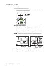
USB In connectors
Two types of USB connectors provide alternative ways to connect the computer to
the HUB4.
b
Captive screw connector — Connect a Type A to unterminated Type B or
mini B USB cable from the computer to this 5-pole 3.5 mm captive screw
connector. (See “Connecting to the captive screw USB connector”, below.)
c
Type mini B USB connector — Connect a Type A-to-mini B USB cable from
the computer to this Type mini B USB connector.
N
Only one host can be connected to the USB In connectors at a time. If two
hosts are connected, the HUB4 defaults to the host attached to the Type mini B
connector.
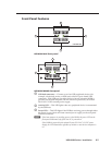
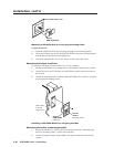
Connecting to the captive screw USB connector
It is recommended that you connect your computer to the HUB4 by plugging the
mini Type B end of the provided USB cable to the USB port on the rear panel. If,
however, your space is limited and you need to use the captive screw USB In
connector instead, prepare and connect the cable as follows:
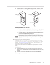
1. Cut off the Type B end of a Type A-to-B or A-to-mini B USB cable. (Do not
remove the Type A plug.)
2. Strip away the exterior jacket and the foil insulation from the unterminated
end of the cable to expose 1 to 2 inches (or 3 to 6 cm) of the wires and shield.
C
Do not cut or remove the braided shield.