


Installation, cont’d
USB HUB4 Series • Installation
2-6
PRELIMINARY
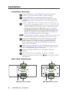
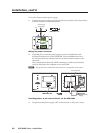
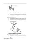
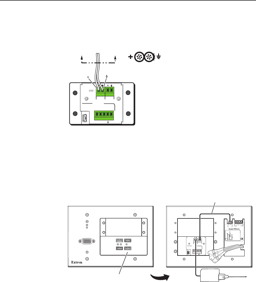
To wire the Extron external power supply,
1. Connect the power supply to the In pins (first and second) of the Power direct
insertion connector as illustrated below.
Power Supply
Output Cord
SECTION A–A
USB IN
WIRE COLOR
RWGB
+V D- D+
S
IN
OUT
WIRE COLOR
RWGB
+V D- D+
S
IN
OUT
A
POWER
500mA
12V
Wiring the power connector
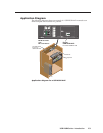
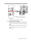
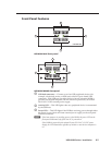
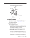
2. (Optional) If you want the power supply to power an additional wall-
mounted Extron device via the USB HUB4, wire the additional device to
the Out pins (third and fourth) of the Power direct insertion captive screw
connector.
The example below shows the HUB4 connected to a WM Series Extender,
which is mounted in the wallplate next to the HUB4.
N
Always take into consideration the total power consumption of the system.
USB IN
12VDC
POWER
WIRE COLOR
RWGB
+VD-D+
S
IN
OUT
WIRE COLOR
RWGB
+VD-D+
S
IN
OUT
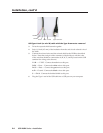
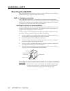
Maximum: Maximum peaking
and gain
Medium: Mid-level peaking
and gain
Normal: Unity gain
Circuit
board
Faceplate
www.extron.com
33-612-01 D
02 05
9-18 VDC
Power
L
Audio
R
Rear
EXTENDER WM AAP
AUDIO IN
USB HUB4 AAP
ACTIVITY
Front
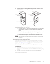
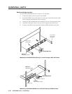
Extender WM AAP
USB HUB4 AAP
Desktop Power
Supply
Power Loop Out
Providing power to an external device via the USB HUB4
3. Plug the external power supply’s IEC connector into an AC power source.