


BBG 6 A • Installation
Installation
BBG 6 A • Connections, Indicators, and Controls
4 5
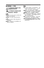
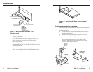
4. For furniture mounting, drill 3/32" (2 mm) diameter pilot
holes, 1/4" (6.3 mm) deep in the mounting surface at the
marked screw locations.
5. For furniture mounting, insert #8 wood screws into the
four pilot holes. Tighten each screw into the mounting
surface until just less than 1/4" (6.3 mm) of the screw head
protrudes.
6. For furniture mounting, align the mounting screws with
the slots in the brackets and place the unit against the
surface, with the screws through the bracket slots.
7. For furniture mounting, slide the unit slightly forward
or back, then tighten all four screws to secure the unit in
place.
8. For projector mounting, secure the unit to a projector
mount or other surface by inserting the mounting bolt
through the bracket’s slotted hole.
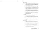
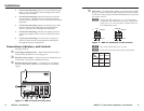
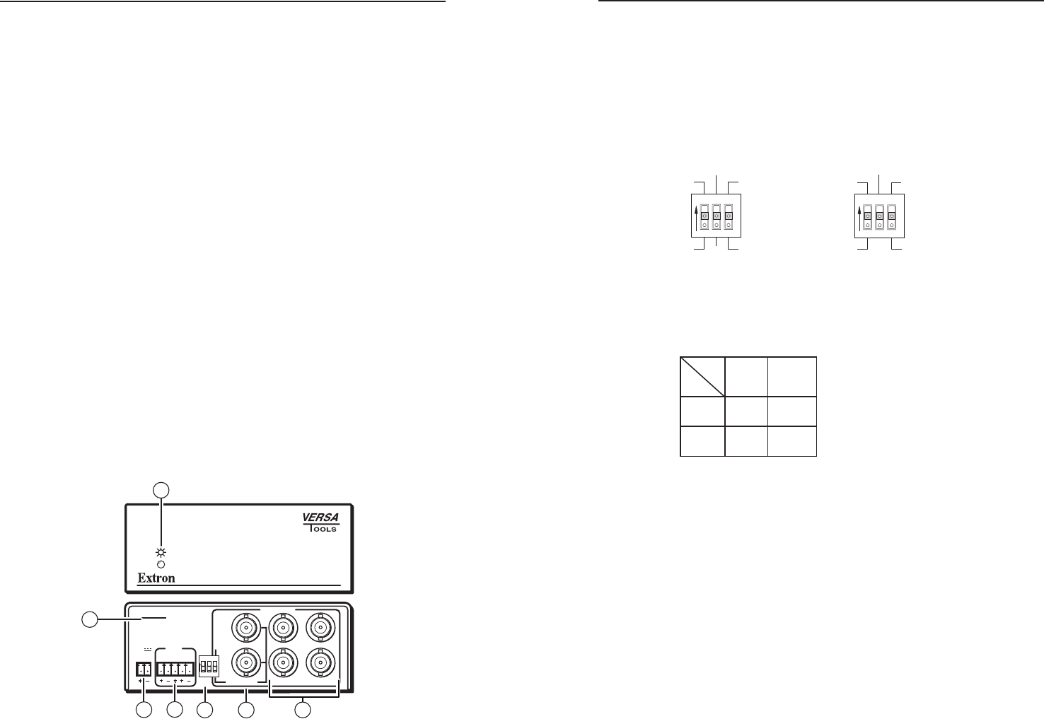
Connections, Indicators, and Controls
See figure 4 below.
a
Power/Signal indicator LED — When illuminated, this LED
indicates that the BBG 6 A is receiving power.
b
Blackburst only outputs — Connect up to four display devices
to these BNC connectors for blackburst output.
c
Blackburst/color bars outputs — Connect up to two display
devices to these BNC connectors for blackburst or color bars
output.
POWER
12V
.2A MAX
L R
4
3
2
1
6
5
PAL
NTSC
BLACKBURST
BLACKBURST
COLORBARS
-10
+4
1 2 3
ON
1 KHZ
AUDIO
BBG 6 A
BLACKBURST AND AUDIO
GENERATOR
1
2
6
3
4
7
5
Figure 4 — BBG 6 A front and rear panels
d
DIP switch — Use these DIP switches to select between +4 dBu
(pro) or -10 dBV (consumer) audio output level, between NTSC
or PAL (USA only) output, and between blackburst or color bars
for outputs 1 and 2.
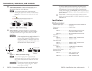
N
With the first DIP switch set to “+4,” the unit outputs
+4 dBu audio level with balanced wiring. With the DIP
switch set to “-10,” the unit outputs -10 dBV audio level
with unbalanced wiring.
NTSC
Blackburst
1
2 3
ON
Color bars
PAL
+4
-10
BBG 6 A
RESERVED
Blackburst
1
2 3
ON
Color bars
+4
-10
BBG 6 A J
Figure 5 — BBG 6 A and BBG 6 A J DIP switches
N
DIP switch 2 of the BBG A J is not used.
N
Please refer to the table below for other combinations.
Output
Dip
Switch
Position
Balanced Unbalanced
+4
-10 -4 dBV
+4 dBu -2 dBu
-10 dBV