


BBG 6 A • Connections, Indicators, and Controls
Connections, Indicators, and Controls
BBG 6 A • Specifications, Parts, and Accessories
6 7
e
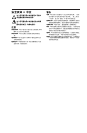
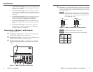
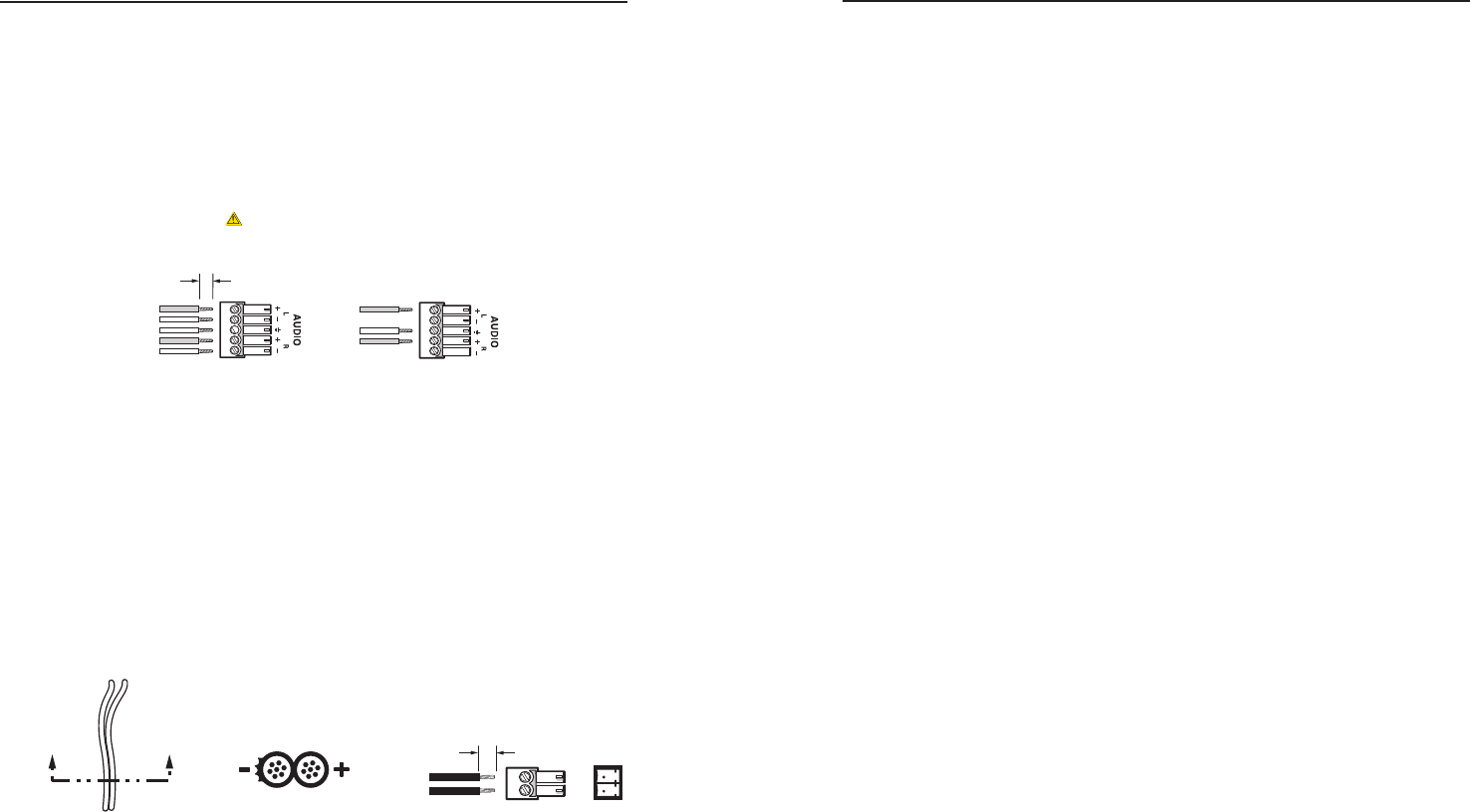
Audio output connector — Insert a 3.5 mm, 5-pole captive
screw connector into this connector for a balanced or
unbalanced 1 kHz sine wave audio tone.
N
Do not tin the stripped power supply leads before
installing the captive screw connector. Tinned wires are
not as secure in the captive screw connectors and could
pull out.
CAUTION
For unbalanced audio, connect the sleeve(s) to the ground contact.
DO NOT connect the sleeve(s) to the negative (-) contacts.
Unbalanced OutputBalanced Output
Tip
Sleeve (s)
Tip
Tip
Ring
Sleeve (s)
Tip
Ring
NO Ground Here
NO Ground Here
3/16" (5 mm) MAX.
Figure 6 — BBG 6 audio wiring
f
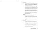
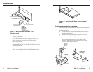
Power connector — Plug the external 12 V power supply
into this 2-pole captive screw connector. The power supply
is included with the unit. Figure 7 shows how to wire the
connector.
C
When connecting the power supply, voltage polarity
is extremely important. Applying power with
incorrect voltage polarity could damage the power
supply and the BBG 6 A. Identify the power cord
negative lead by the ridges on the side of the cord or
the black heat shrink wrapping around it.
Power Supply
Output Cord
Captive Screw
Connector
A A
SECTION A–A
12 V
3/16” (5 mm) MAX.
+ +
- -
Figure 7 — Power connector wiring
N
Do not tin the stripped power supply leads before
installing the captive screw connector. Tinned wires are
not as secure in the captive screw connectors and could
pull out.
W
The two power cord wires must be kept separate
while the power supply is plugged in. Remove
power before continuing.
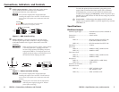
To verify the polarity before connection, plug in the power
supply with no load and check the output with a voltmeter.
As an alternative, you can use an Extron P/S 100 Universal
12 VDC Power Supply (part #60-357-01), which can power up to
ten BBG 6 As or other Extron 12 VDC devices using only one AC
power connector.
g
Version label — Differentiates the standard (NTSC and PAL
signals) versus Japanese (BBG 6 A J, NTSC signals only) versions
of the BBG 6 A.
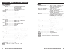
Specifications
Blackburst output
Number/signal type ..................... 6 blackburst (two can be switched to
color bars)
Connectors ..................................... 6 BNC female
Standards
BBG 6 A ............................... RS-170A standard for NTSC 3.58,
CCIR 624-4 standard for PAL
BBG 6 A J............................. RS-170A standard for NTSC 3.58
Impedance ..................................... 75 ohms
Sync level
BBG 6 A ............................... 40 IRE for NTSC, 43 IRE for PAL
BBG 6 A J............................. 40 IRE for NTSC
Color burst level
BBG 6 A ............................... 40 IRE for NTSC, 43 IRE for PAL
BBG 6 A J............................. 40 IRE for NTSC
Setup level
BBG 6 A ............................... 7.5 IRE (NTSC) or 0 IRE (PAL)
BBG 6 A J............................. 0 IRE (NTSC)
Tolerance for all levels .................. ±3%
Subcarrier levels
BBG 6 A ............................... NTSC 3.579545 ±3 Hz
PAL 4.433618 ±3 Hz
BBG 6 A J............................. NTSC 3.579545 ±3 Hz