


3-13CrossPoint Matrix Switchers • Operation
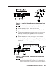
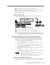
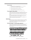
A
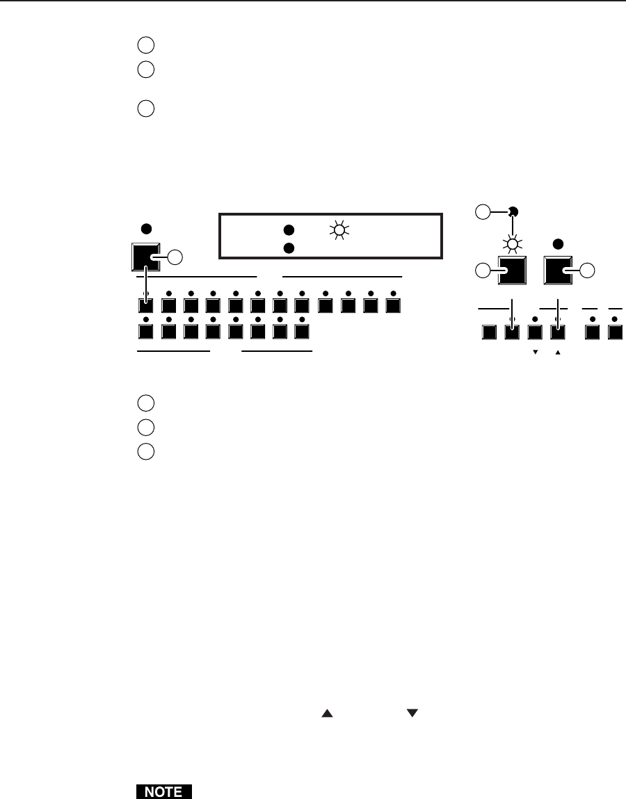
Press and release the Esc button. The Esc LED flashes once.
B
Press and hold the Preset button for approximately 2 seconds until the Preset
LED begins to blink, then release the Preset button.
C
Press and release the input 1 button. The input 1 LED flashes once. The
Preset LED turns off.
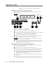
Example 7: Recall a preset
See figure 3-14 and the following steps for an example of recalling a preset to
become the current configuration.
1
1
2
2
3
3
4
4
5
5
6
INPUTS
ENTER
OUTPUTS
6
7
7
8 9 10 11
PRESET VIEW ESC RGBHV AUDIO
12
8
CONTROL I/O
ESC
A
1
C
PRESET
B
C
LED key: = off, = on
= on for 2 seconds, then off
F
F
F
Press
Press
Press
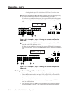
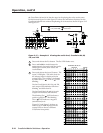
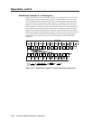
Figure 3-14 — Example 7: Recalling preset 1
A
Press and release the Esc button. The Esc LED flashes once.
B
Press and release the Preset button. The Preset LED lights.
C
Press and release the input 1 button. The input 1 LED flashes once. The
Preset LED turns off. The configuration stored in memory location 1 is now
the current configuration and can be viewed in the view-only mode (Example
4).
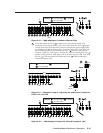
Viewing and adjusting the audio level (HVA models only)
On HVA models, the audio level of each input can be displayed and adjusted
through a range of -15dB to +9dB to ensure that there is no noticeable volume
difference among sources. The audio level can be adjusted from the front panel or
by using Extron’s Windows-based control program.
1. Press and hold the Audio button until the Audio LED begins to blink, then
release the Audio button.
2. Press and release an input button to select an input. The audio level for the
selected input is displayed in the output LEDs and the polarity (+ or -) is
displayed in the View or Esc LEDs.
3. Press and release the Esc (
) and View ( ) buttons to increase and decrease
the audio level.
4. Press and release the Audio button to exit the audio display and adjust mode.
The Audio LED stops blinking and turns off.
1. There is one audio level setting per input. The audio level setting is
shared by the left and right audio inputs.
2. The audio level settings are stored in non-volatile memory. When power
is removed and restored, the audio level settings are retained.
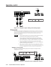
Example 8: View and adjust an audio level
See figure 3-15, figure 3-17, and the following steps for an example of viewing and
adjusting the audio level. Audio gain and attenuation is displayed differently on