


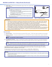
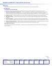
a Power input — Connect the provided power suppy to the 3.5 mm, captive screw
12V
0.4A MAX
POWER
Power Supply
Output Cord
SECTION A–
A
RidgesSmooth
AA
DC Power Cord
Captive Screw Connector
AC Power Cord
Ground
+12 VDC
External
Power Supply
(12 VDC, 1 A )
power receptacle.
NOTES:
• The length of the exposed wires in the stripping process is critical.
The ideal length is 3/16 inch (5 mm).
• If the exposed section is longer, the exposed wires may touch,
causing a short circuit between them.
• If it is shorter, the wires can be easily pulled out, even if tightly
fastened by the captive screws.
• Do not tin the wires. Tinned wire does not hold its shape and can
become loose over time.
Figure 4. Power Connection
ATTENTION:
• This product is intended to be supplied by a Listed Power Unit marked “Class 2” or “LPS,” rated 12 VDC, maximum
1.0 A. Always use a power supply supplied or specied by Extron. Use of an unauthorized power supply voids all
regulatory compliance certication and may cause damage to the supply and the end product.
• Unless otherwise stated, the AC/DC adapters are not suitable for use in air handling spaces or in wall cavities. The
power supply is to be located within the same vicinity as the Extron AV processing equipment in an ordinary location,
Pollution Degree 2, secured to the equipment rack within the dedicated closet, podium, or desk.
• The installation must always be in accordance with the applicable provisions of National Electrical Code ANSI/NFPA70,
article 75, and the Canadian Electrical Code part 1, section 16. The power supply shall not be permanently xed to
building structure or similar structure.
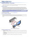
DVI Connections
b Input connector — Connect the input signal to the female DVI connector. The DVI input signal is equalized to ensure integrity.
c Output connectors — Connect up to two (DVI DA2) or four (DVI DA4) DVI-D outputs to display devices, using the female DVI
connectors.
NOTE: The outputs are not HDCP compatible.
d Local Monitor connector — Output 1 (Local Monitor) is used as a Hotplug Detect, a DDC clock, and a DDC data reference.
For the input device to provide a signal at the correct resolution and refresh rate, there must be a display device connected to
output1.
NOTE: Although the source device, local monitor, and remote display devices all connect to the distribution amplifiers
through DVI-I connectors, the DVI DA2 and DVI DA4 are compatible only with single-link DVI-D video signals.
To enable the units to accept sources providing HDMI signals or to provide signals to displays that accept HDMI signals,
use a HDMI to DVI adapter or cable, such as the Extron HDMIF-DVIDM female HDMI to male DVI-D adapter or the Extron
HDMIM-DVI-D M series of male HDMI to male DVI cables.
The input signal is one single link DVI-D with a resolution range up to 1920x1200 or 1080p@ 60 Hz.
Input EQ conditions input signals to ensure the integrity of the signals delivered to the output devices.
NOTES:
• The actual signal transmission distance can vary and depends on the signal resolution, cable quality, graphics card, and
display used in the system.
• To ensure proper operation, display devices connected to outputs 2 through 4 must be able to handle resolutions equal
or greater than that of the local monitor on output 1.
3
DVI DA2 and DVI DA 4 • Setup Guide (Continued)