


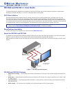
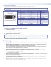
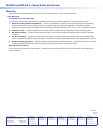
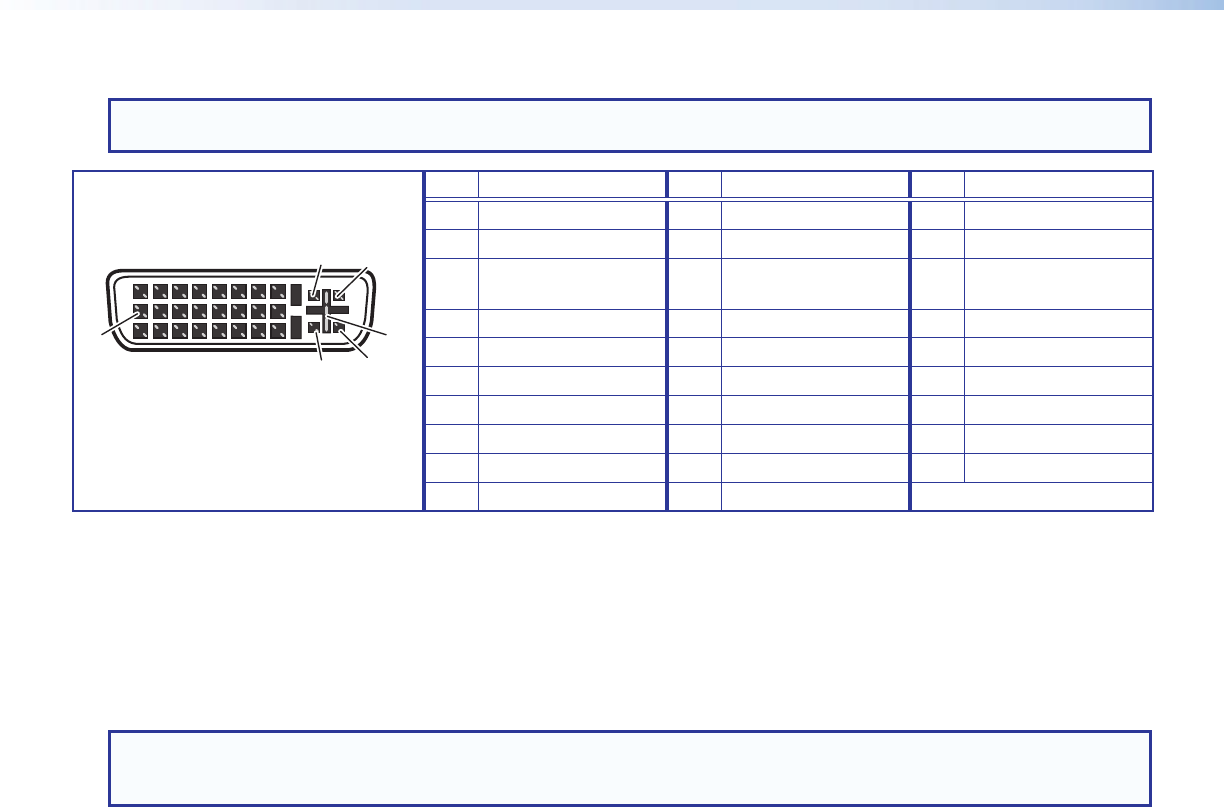
DVI Connector Pin Assignments
The illustration below shows the pin assignments for the male and female DVI-I connectors.
NOTE: Although DVI-I dual link connectors are used, the DVI DA2 and DVI DA4 are compatible only with single-link DVI-D
video signals.
Pin
Signal
Pin
Signal
Pin
Signal
Three rows of eight holes and two contacts
above and below the "+" socket.
DVI-I Dual Link - Female
(analog and digital)
1
9
8
17 24
C3 C4
C1 C2
C5
1 TMDS data 2- 9 TMDS data 1- 17 TMDS data 0-
2 TMDS data 2+ 10 TMDS data 1+ 18 TMDS data 0+
3 TMDS data 2/4
shield
11 TMDS data 1/3
shield
19 TMDS data 0/5
shield
4 TMDS data 4- 12 TMDS data 3- 20 TMDS data 5-
5 TMDS data 4+ 13 TMDS data 3+ 21 TMDS data 5+
6 DDC clock 14 +5V power 22 TMDS clock shield
7 DDC data 15 Ground 23 TMDS clock+
8 Analog vertical sync 16 Hot plug detect 24 TMDS clock1
C1 Unused C3 Unused C5 Unused
C2 Unused C4 Unused
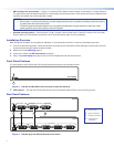
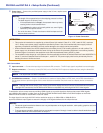
Operation
To operate the unit (see figure 3 on page 2 and figure 4 on page 3):
1. Connect the power supply.
2. Connect and power on the Local Monitor.
3. Connect and power on any other output displays.
4. Connect and power on the source device.
NOTE: Output 1 (Local Monitor) is used as a DDC reference and must be connected to the distribution amplifier before the
source device is powered on. If the source device cannot communicate with the local monitor when it is being powered
on, it may not be able to send a video signal or the signal may have the wrong resolution or refresh rate.
If there are any problems, consult the Troubleshooting section below.
Troubleshooting
• No output signal — Check that the front panel LED is lit. If it is not, check the power supply connections to the unit (see
page 4).
• No output signal or poor quality signal — Check the integrity of the cabling to output1 (Local Monitor) and ensure that
output 1 is connected to the distribution amplier before powering on the source device.
If the source device cannot communicate with output 1 when it is being powered on, it may not be able to send a video
signal or the signal may have the wrong resolution or refresh rate.
• No output signal or poor quality signal — Check the input and output cabling (page3). DVI signals run at very high
frequency and poor connections can cause degradation or loss of the signal, or jitter. To avoid this:
• Use only cable that is designed for DVI signals.
• Limit or avoid the use of adapters.
• Display device shows a flashing black or blue screen, snow or other distortion — A device that is not HDCP compliant
may be receiving HDCP-encrypted signals.
The DVI DA2 and DVI DA4 are not High-Bandwidth Digital Content Protection (HDCP) compliant. They will pass HDCP-
encrypted signals only to the local output device.
• Signal on local monitor but not on other displays — Check that all output devices (monitors or projectors) can handle
resolutions equal to or greater than that of the local monitor.
4