


DVI Output Card Installation
Installation
1
An optional digital visual interface (DVI) output card is available for
the ISS 108, ISS 408, and ISM 482. With the card installed, the switcher
outputs Program video simultaneously on the standard DVI connector
and Program Output BNC and 15-pin HD connectors.
Opening the Switcher
Extron recommends returning the switcher to Extron for service and
updates.
N The ISM 482 Switcher installation is shown. The ISS 108 and
ISS 408 installations are similar.
To install the optional DVI output card, the switcher case must be
removed.
Remove as follows:
1. Disconnect the AC power cord to remove power from the switcher.
W To prevent electric shock, always unplug the switcher from
the AC power source before opening the enclosure.
2. If the switcher is installed in a rack, disconnect all signal and
control cables and remove the switcher from the rack.
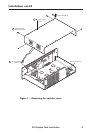
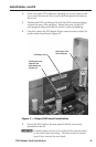
3. Remove the 16 screws from the switcher, 8 on the top and 4 on
each side of the cover (figure 1).
4. Remove the top two front panel screws.
5. Lift the top cover straight up approximately five inches for access
to the fan power cords.
C Do not touch any switches or other electronic components
inside the switcher. Doing so could damage the switcher.
Electrostatic discharge (ESD) can damage IC chips even
though it cannot be felt. A grounding wrist strap is
recommended.
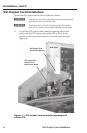
6. Disconnect the two fan power cords from connectors J8 and J13 on
the main board.
7. Remove the top cover and set it aside.