


FOX Matrix 3200 and FOX Matrix 7200 • Front Panel Operations 1110 FOX Matrix 3200 and FOX Matrix 7200 • Installation
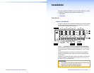
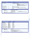
Front Panel
FOX 4G MATRIX 3200
FIBER OPTIC DIGITAL MATRIX SWITCHER
POWER SUPPLY
PRIMARY
REDUNDANT
CONTROL
ENTERPRESET
VIEW
ESC
CONFIG
2
1
A
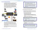
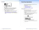
Configuration port — If desired, connect a control system or
computer to the front panel Configuration (RS-232) port. Use an
optional 9-pin D to 2.5 mm mini jack TRS RS-232 cable.
B
Primary and Redundant Power Supply LEDs —
Green — Indicates that the associated power supply is operating
within normal tolerances.
Red — Indicates that the associated power supply is operating
outside the normal tolerances or has failed (see Removing and
Installing a Power Supply Module on page 29 to replace the power
supply).
Front Panel Operations
This section describes simple matrix switcher operation from the front
panel. Topics that are covered include:
• Creating a Tie
• Viewing Ties (and Muting Outputs)
• Saving or Recalling a Preset
• Locking the Front Panel (Executive Mode)
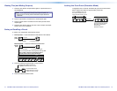
Creating a Tie
A "tie" is an input-to-output connection.
A "set of ties" is an input tied to two or more outputs. (An output can
never be tied to more than one input.)
A "conguration" is one or more ties, one or more sets of ties, or a
combination.
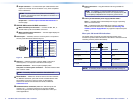
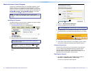
1. Press and release the Esc button to clear any input button, output
button, or control button indicators that may be lit.
2. Press and release the desired input button.
5
The button lights to indicate the selection.
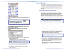
3. Press and release the desired output buttons.
3 4
ENTER
8
The output buttons blink to indicate the potential ties.
The Enter button b
links to indicate
the need to confirm the change.
4. Press and release the Enter button. The tie is created and all button
indicators turn off.