


HSA 200/222 Series • Installation
HSA 200/222 Series • Installation
Installation, cont’d
All HSA 200 and HSA 222 models
4
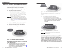
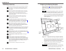
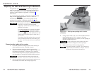
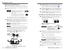
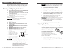
Screw clamp bracket/screw clamp — These two brackets/
clamps hold the enclosure firmly in place in the mounting hole.
5
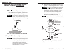
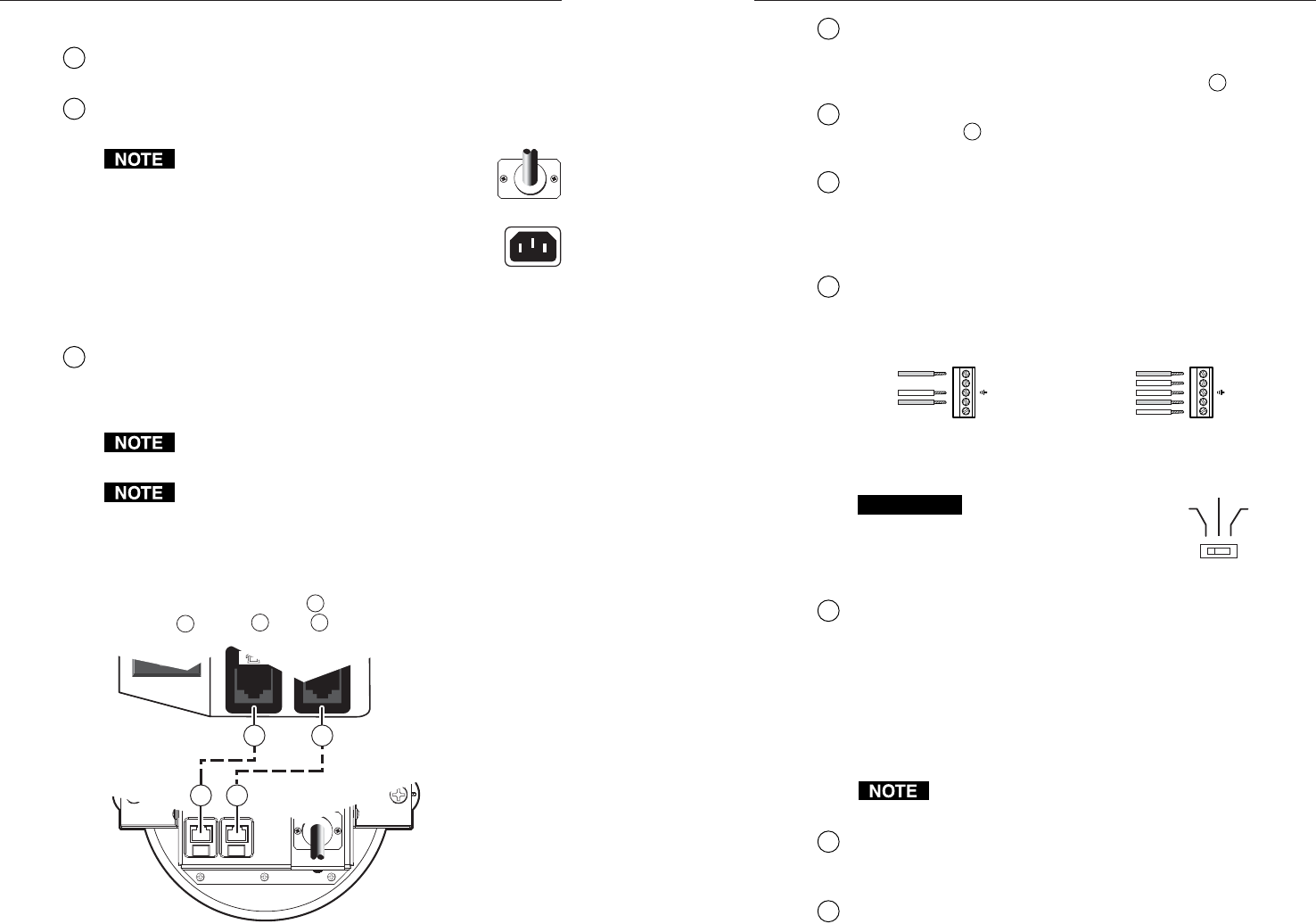
AC power input connection — Connect this cord to the power
source.
For US-domestic versions, this power cord is
permanently connected to the HSA.
Connect the power cord to a 125VAC, 60 Hz,
5A power source.
For international versions, this power cord is a
removable IEC power cord. Connect the cord
to a 220-240V, 50/60 Hz, 5A power source.
You can replace this connector with an optional Extron HSA 200/
HSA 222 Flexible Conduit Adapter kit (part #70-229-01).
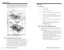
6
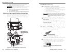
RJ-45 connectors — Plug one end of a CAT 5 or CAT 6 twisted
pair (TP) cable into each of these RJ-45 female connectors.
Connect the other end to an appropriate telecommunications or
data network or to an Extron TP product.
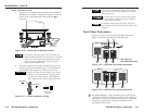
All RJ-45 connectors are teminated in accordance with
the TIA/EIA 568 A standard.
An RJ-11 plug can be connected to the RJ-45 jack.
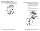
When cabling the front panel and the underside of the enclosure
(figure 2-8), ensure that the bottom RJ-45 connections match up
with the front panel RJ-45 connector locations. For example,
match the front panel RJ-45 (CAT 6) network, data, or
communications connection
5A
with the underside RJ-45
connector
6A
, match
5B
with
6B
and so forth.
Bottom View
6B 6A
Front View
5A 5B
Figure 2-8 — Configuration of RJ-45 connectors
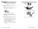
7
Latch locking screws — These screws secure the latching
mechanism to the enclosure. They must be loosened in order to
adjust the top surface (see “Adjusting the Top Panel” in
chapter 3) with the top surface adjustment screw
8
.
8
Top surface adjustment screw — After loosening the latch
locking screws
7
, adjust the top surface of the tilt up panel with
this screw. Tighten the latch locking screws after adjustment.
9
Gas lift mounting plate — The lower end of the gas lift is
attached to this plate. The plate must be detached from the
enclosure in order to remove the gas lift.
HSA 200CE and HSA 200SE (Extender board) only
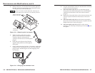
10
Audio output connection — This 5-pole direct insertion
terminal outputs unbalanced or balanced audio. Figure 2-9
shows how to wire the connector.
Unbalanced Output
Tip
See Caution
Sleeve (s)
Tip
See Caution
Balanced Output
Tip
Ring
Sleeve (s)
Tip
Ring
L
+
L
-
R
+
R
-
Audio
L
+
L
-
R
+
R
-
Audio
Figure 2-9 — Extender board audio
connector wiring
CAUTION
Connect the sleeve to
ground (Gnd).
Connecting the sleeve to a
negative (-) terminal will
damage the audio output circuits.
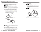
11
Gain switch — To compensate for cable resistance and
capacitance, use a Tweeker to slide this switch to select the level
of video gain that yields the sharpest, smear-free picture.
Normal — unity gain (no signal boost)
Medium — mid-level peaking and gain
Maximum — maximum amount of peaking and gain. Select
this setting for use with longer cables.
Adjust the gain before installing the HSA unit, as the
gain switch may be inaccessible after installation.
12
Power supply connection — Plug the external power supply
(included) output wires into this 2-pole direct insertion
terminal. See “Power connector wiring” to wire the connector.
13
Power LED — Indicates when the Extender board is receiving
power.
2-10 2-11
NORMAL
Unity Gain
MEDIUM
Peaking and Gain
MAXIMUM
Peaking and
Gain