


HSA 200/222 Series • Installation
HSA 200/222 Series • Installation
Installation
2-3
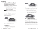
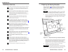
Preparing the Routing Template
Extron provides a metal template for each HSA model at no
charge. Appendix A lists the HSA 200 and HSA 222 template
part numbers. Extron recommends using this template as a
guide to cut the hole in the table where the HSA will be
installed.
The metal routing template is reusable. Do not discard
this template when the installation is complete. Save it
for installing future HSA enclosures of the same size.
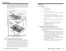
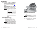
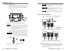
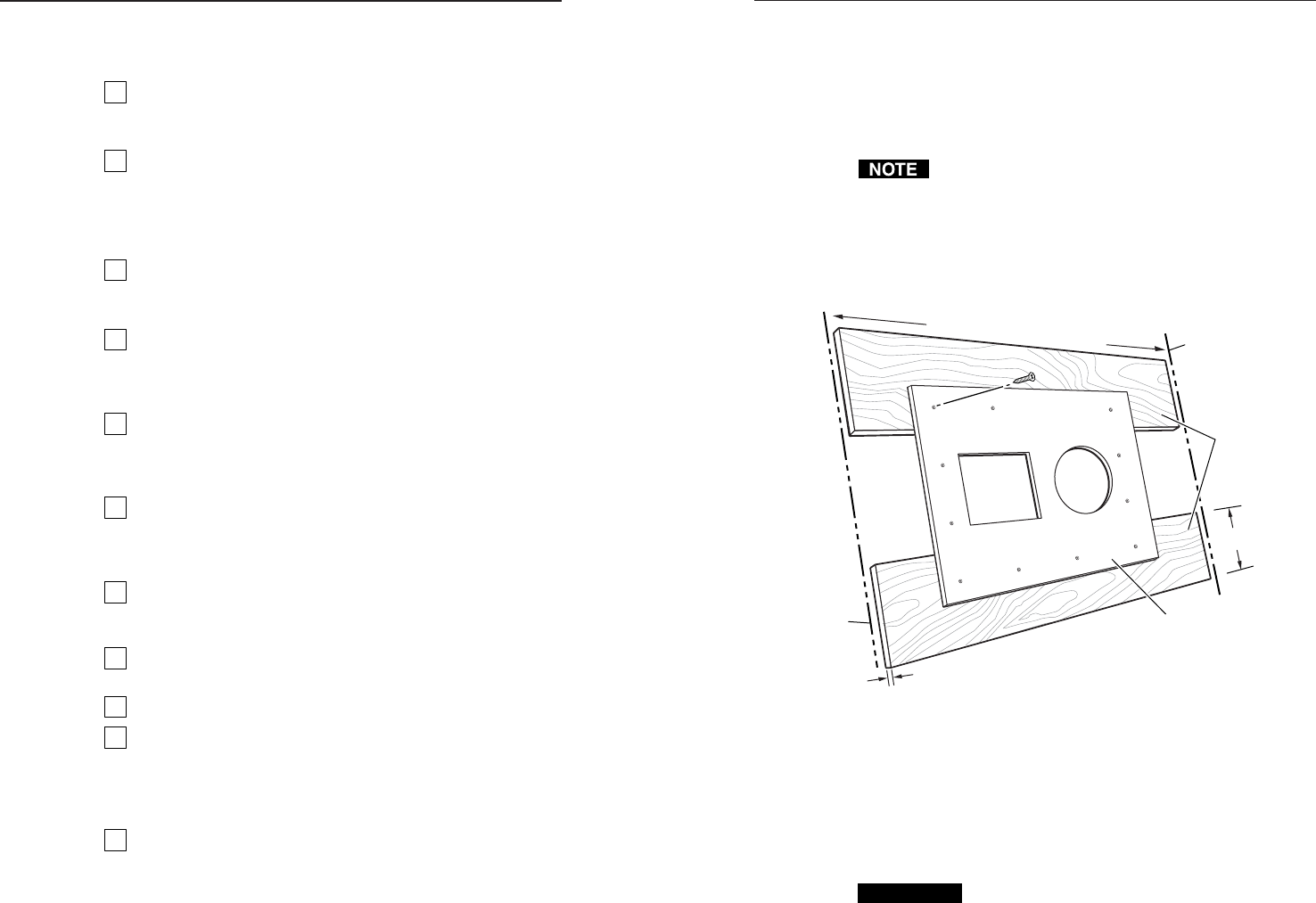
1. Cut 1/2" x 4" strips of soft, finished lumber long enough to
span the distance between the desired installation location
on the mounting surface and the edges of the mounting
surface (figure 2-1).
Mounting
Surface
Edge
Mounting
Surface
Edge
Wood Thickness
0.5" / 1.3 cm
Width of Mounting Surface
Routing Template
Wood Strip
Height
4" / 10.2 cm
Minimum
4 Screws
Wood
Strips
Figure 2-1 — Prepared mounting template assembly
These strips raise the routing template above the mounting
surface to provide room for the router’s collar, protect the
mounting surface, and extend the reach of the routing
template so that it can be clamped to the edge of the surface.
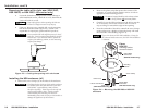
2. Using four or more short wood screws, secure the
mounting template to the lumber strips.
CAUTION
Do not allow the wood screws to protrude through
the bottom of the wooden strips. Protruding screws
will mar the table when the template is used.
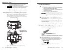
Installation Overview
Install and set up the HSA surface access enclosures as follows:
1
If you have an unprepared mounting template, prepare
the template. See “Preparing the Routing Template” in
this chapter.
2
If desired, install the optional RJ-45 to RJ-11 conversion
kit(s) to replace one or more RJ-45 connectors with RJ-11
connectors. Refer to the appropriate RJ-45 to RJ-11
Conversion Kit manual, for either the HSA 200 models or
the HSA 222 models.
3
If desired, install the optional flexible conduit kit to
replace the removable AC power cord. Refer to the
Flexible Conduit Kit manual.
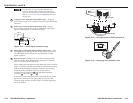
4
Cut a hole in the surface where the enclosure will be
installed and install the enclosure. The screw clamps
secure the enclosure to the tabletop. See “Preparing the
Table and Mounting the Enclosure” in this chapter.
5
Run all cables necessary to support the AC power,
RJ-45, and (for HSA 200 model only) video and audio
connectors. Leave enough slack in the cables to connect
them to the underside of the enclosure.
6
Turn off all of the equipment to be connected. Ensure that
the equipment connected to the RJ-45, video, and audio
connectors are all turned off and disconnected from the
power source.
7
Connect the power, video, audio, and RJ-45 cables to the
underside of the enclosure. See “Underside Features and
Cabling Connections” in this chapter.
8
On HSA 200SE and HSA 200CE models, set the gain
switch.
9
Connect and turn on the input and output devices.
10
For HSA 200SE and HSA 200CE model installations, the
picture should now appear and sound should be audible.
If not, ensure that all devices are plugged in and receiving
power. Check the cabling and gain setting, and make
adjustments as needed.
11
Peel the protective coating from the top surface.
2-2