


IN1124/28/30 Transmission System • Installation and Operation
Installation and Operation, cont’d
IN1124/IN1128/IN1130 Transmission System
A
Appendix A
Reference Information
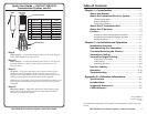
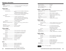
Specifications
Included Parts
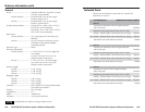
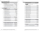
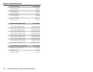
Accessories
Installation Kits
Cables/Adapters
Operation
9
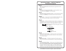
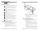
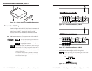
Power — Plug the external 9V power supply into this power
connector. The power supply is included with the unit. Plug
the power supply into a 100 to 240VAC, 50 Hz or 60 Hz power
source.
Alternatively, an Extron P/S 100 Universal 12VDC Power
Supply can power up to six transmitters or receivers using only
one AC power connector.
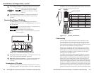
10
Power LED — Lights to indicate that power is applied.
11
Sharpness control — Adjusts the sharpness of both images
simultaneously. Use a Tweeker or other small, flat-head,
screwdriver to adjust the control.
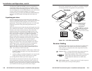
Troubleshooting
1. Ensure that all devices are receiving power. The
transmitter’s and receiver’s front panel Power LEDs
indicate that they are receiving power.
2. Ensure that the transmitter is receiving a video input.
3. Ensure that the TP cable(s) are properly terminated in
accordance with TIA/EIA T 568A or TIA/EIA T 568B
standards and that the RJ-45 connections are securely
made.
4. The transmission distance may be too short. Ensure that
the UTP cable is at least 50 feet long.
5. The transmission distance may be too long. Try
shortening the distance between the transmitter and
receivers.
6. Call the Extron S
3
Sales & Technical Support Hotline if
necessary.
2-10