


IN1124/28/30 Transmission System • Quick Start Guide
Quick Start Guide — IN1124/1128/1130
Transmission System, cont’d
IN1124/28/30 Transmission System • Table of Contents
Chapter 1 • Introduction....................................................... 1-1
About this Manual ............................................................ 1-2
About the Transmitter/Receiver System ..................1-2
TP cable advantages .............................................................. 1-2
System distribution ................................................................1-2
Transmission distance ............................................................ 1-2
About the TP Transmitter/DAs...................................... 1-3
About the TP Receiver ..................................................... 1-4
Features ................................................................................. 1-4
IN1124 TP transmitter/distribution amplifier....................... 1-4
IN1128 TP transmitter/distribution amplifier....................... 1-5
IN1130 TP receiver ................................................................. 1-5
Chapter 2 • Installation and Operation ......................... 2-1
Installation Overview ..........................................................2-2
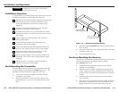
Rack Mounting the Transmitter ..................................... 2-2
Furniture Mounting the Receiver ................................. 2-3
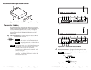
Transmitter Cabling.............................................................. 2-4
Transmitted Signal Cabling .............................................. 2-6
Termination of TP cable ........................................................ 2-6
Cable testing .......................................................................... 2-7
Equalizing pair skew ............................................................. 2-8
Receiver Cabling .................................................................... 2-9
Operation................................................................................. 2-10
Troubleshooting ................................................................... 2-10
Appendix A • Reference Information ............................ A-1
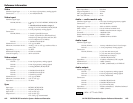
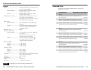
Specifications ......................................................................... A-2
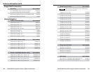
Included Parts ......................................................................... A-5
Suggested Accessories....................................................... A-6
Cables/Adapters .................................................................... A-6
Table of Contents
68-754-01 Rev. A
Printed in the USA
12 02
All trademarks mentioned in this manual are the properties of their respective
owners.
i
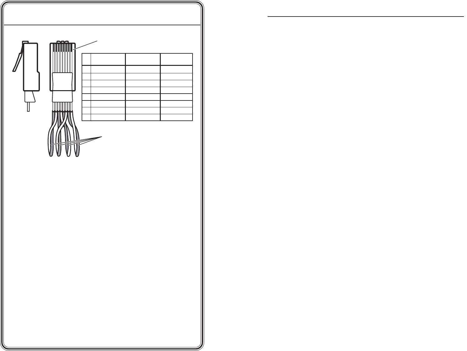
Clip DownSide
1
1&2
3&6 4&5
7&8
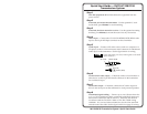
2345678
12345678
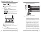
Pin Signal
1 Red/V. sync+
2 Red/V. sync-
3 Green/H. sync+
4 Blue+
5 Blue-
6 Green/H. sync-
7 Mono audio +
8 Mono audio -
RJ-45 connector
Twisted Pairs
Wire color
White-green
Green
White-orange
Blue
White-blue
Orange
White-brown
Brown
Wire color
TIA/EIA T 568 A TIA/EIA T 568 B
White-orange
Orange
White-green
Blue
White-blue
Green
White-brown
Brown
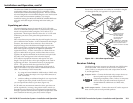
Step 9
Video outputs — Connect the desired video devices to the Output
15-pin HD connectors on each receiver.
Step 10
Audio outputs — Connect the desired audio devices, such as local
powered speakers, to these 3.5 mm jacks on each receiver. The
output is mono.
Step 11
AC power — Plug the external 9V power supply into the power
connector on the transmitter and all receivers. Plug the power
supplies into a 100 to 240VAC, 50 Hz or 60 Hz power source. Each
unit has a power LED that indicates that power is applied.
Alternatively, an Extron P/S 100 Universal 12VDC Power Supply can
power up to six transmitters or receivers using only one AC power
connector.
Step 12
Sharpness control — Adjust the sharpness of both output images
from each receiver by using a Tweeker or other small, flat-head,
screwdriver to adjust the control.