


3
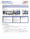
RS-232 and IR Over TP Wiring (IN1604 DTP Only)
To pass bidirectional serial command signals between the IN1604 DTP and a connected DTP or HDBaseT sink device, connect a control device to
the three leftmost poles (Tx, Rx, and G) of the 5-pole captive screw connector. To transmit and receive IR signals, connect a control device to the
three rightmost poles (G, Tx, and Rx).
NOTE: RS-232 and IR data can be transmitted or received simultaneously.
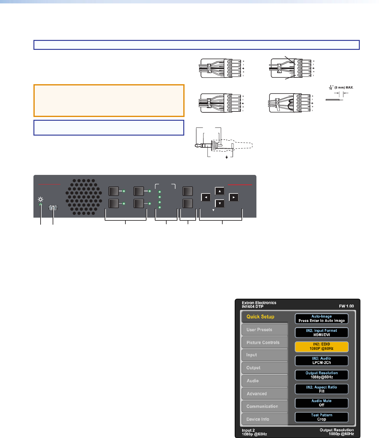
Audio Wiring
Wire the 3.5 mm, 5-pole captive screw audio input and output
connectors as shown to the right. Use the supplied tie wrap to strap
the audio cable to the extended tail of the connector.
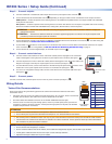
ATTENTION: For unbalanced outputs, do not connect
wires to the “-” poles.
ATTENTION : Pour les sorties asymétriques, ne connectez
pas de câbles aux pôles «-».
NOTE: The length of exposed wires is critical. The ideal
length is 3/16 inch (5 mm).
Wire the TRS audio input connector as shown in the 3.5 mm Stereo
Plug Connector diagram to the right.
Front Panel Overview
IN1604 DTP
Extron
HDCP
MENU
2
4
1
3
ENTER
AUTO-
IMAGE
INPUT 2
HOLDFOR XGA/720p
INPUT 3
INPUT 4
OUTPUT
CONFIG
BCDE FA
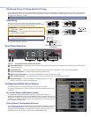
Figure 2. Front Panel Features (IN1604 DTP Shown)
A
Power LED indicator — Lights green when the scaler is receiving power and a signal on the selected input. Lights amber when the scaler is
receiving only power.
B
Configuration port — Connect a host device to the USB mini-B port for device conguration, control, and rmware upgrades.
C
Input selection buttons — Press one of these buttons to select an input.
D
HDCP status LED indicators — Light when the HDMI inputs or output are HDCP encrypted.
E
Menu and Enter buttons — Press these buttons to access and navigate the on-screen display menu system.
F
Navigation buttons — Press these buttons to navigate through the on-screen
display menu system or change selected settings.
Conguring IN1604 Series Scalers
The IN1604 Series can be congured through front panel controls and the
on-screen display (OSD) menu, the Extron Product Conguration Software (PCS), or SIS
commands.
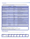
On-screen Display (OSD) Menu System
To congure the IN1604 Series using the OSD menu, connect a DTP receiver or
HDBaseT-compatible device with a connected display to the TP output connector on the
IN1604 DTP or a display to the HDMI output connector on the IN1604 HD. The OSD menu
consists of nine submenus (see the example to the right) that can be accessed using the
front panel Menu or Enter button.
Extron Product Conguration Software
To congure the IN1604 Series using the PCS, install the software (available on the Extron
website, www.extron.com) to a PC connected to the scaler via the front panel USB
Cong port. After the installation, start the program. For full instructions, press <F1> on
the keyboard or click the ? button in the software and select Help File.
Balanced Audio Output
Tip
Ring
Tip
Ring
Slee
ves
Unbalanced Audio Output
Tip
No Ground Here
No Ground Here
Tip
Sleeves
LR
LR
Unbalanced Audio InputBalanced Audio Input
Tip
Ring
Tip
Ring
Slee
ves
Tip
Sleeve
Sleeve
Tip
LR
LR
Do not tin the wires!
Tip (+)
Sleeve ( )
Sleeve ( )
Ring (
-
)
Tip (+)
Audio Plugs.eps
RCA Connector
3.5 mm Stereo Plug Connector
(balanced)
Sleeve ( )
Ring (R)
Tip (L)
3.5 mm Stereo Plug Connector
(unbalanced)