


2
IPATRLY4•Connections
Connections
N
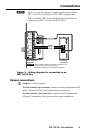
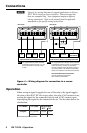
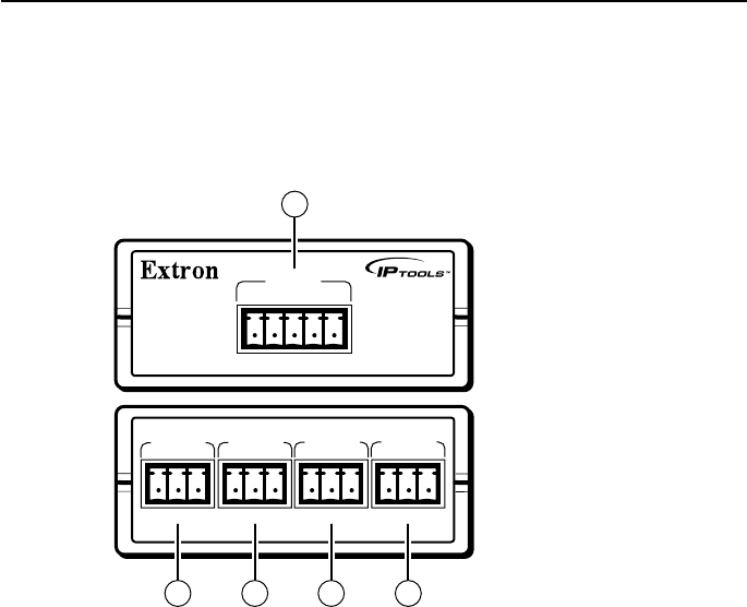
The 5-pole captive screw input connector and four 3-pole captive
screw output connectors are included with the unit, but you
must supply the cable. Extron recommends its CTL Series cable,
part #22-148-nn (non-plenum bulk rolls), 26-119-nn (plenum
bulk rolls), or 26-461-nn (plenum pre-cut lengths).
IPA T RLY4
1 2 3 4 C
INPUTS
NO C NC
NO C NC NO C NC NO C NC
RELAY 1
RELAY 2
RELAY 3
RELAY 4
2 2 2 2
1
Figure 2 — IPA T RLY4 connections
Input connections
a
Inputs — Connect the 12 VDC source to the common voltage (C)
terminal of the 5-pole captive screw connector. Connect the
appropriate input terminal (1 through 4) to the digital output(s) of
the IPL T SF24, MLC 104 IP Plus, or other device.
C Connect +12 VDC to the C pin only and
connect the return to one or all of the Input pins
(1 through 4) for the relays that you will use.
Reversing the connections can damage the power
supply.
N
Connect the I/O control line to the Input 1 terminal for
relay 1, Input 2 for relay 2, and so on.