


IPATRLY4•Connections
3
Connections
N
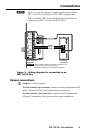
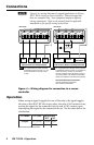
Figure 3 is a wiring diagram of a typical application: an Extron
MLC 104 IP Plus controlling an IPA T RLY4 relay function.
Refer to the MLC 104 Plus Series Manual for information on
configuring the MLC to control the IPA T RLY4.
1
2
3
GROUND
+12V OUT
CM
GROUND
IR OUT
GROUND
SCP
GROUND
Tx
Rx
DISPLAY
RS-232/IR
A B C D E
COMM LINK
LAN
PRESS TAB WITH
TWEEKER TO REMOVE
A B
MLS
RS-232
POWER
12V
DIGITAL
I/O
IR IN
Tx
GROUND
Rx
+12V IN
IPA T RLY4
1 2 3 4 C
INPUTS
MLC 104 IP Plus
Right Side
Observe proper polarity when making connections to the
MLC 104 IP Plus controller’s Power port.
Miswiring can damage the controller’s Digital I/O port.
IPA T RLY4
Front Panel
Relay 1
Relay 2
Relay 3
+12 VDC
CAUTION
Figure 3 — Wiring diagram for connection to an
MLC 104 IP Plus
Output connections
b
Outputs — For each relay:
For the normally open contacts, connect a device between the NO
and C terminals of the 3-pole captive screw connectors.
For the normally closed contacts, connect a device between the
NC and C terminals of the 3-pole captive screw connectors.