


3CrossPoint Plus/CrossPoint/MAV/Matrix 50 • Firmware Upgrade Procedure
Remove the front panel
Before you can replace the firmware IC, you must remove the matrix switcher’s
front panel as follows:
Power must be disconnected the cord from the switcher.
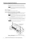
1. If the switcher has screws on its top and bottom, remove the two top and
bottom screws (four screws total) on the front of the switcher (figure 1).
These screws are present and need to be removed only if the matrix switcher
to be updated is
not one of the following models:
• CrossPoint Plus 168 • CrossPoint Plus 1616
• CrossPoint 168 • CrossPoint 1616
2. Remove the four or ten (depending on the switcher model) that secure the
switcher’s front panel in place.
3. Carefully tilt the front panel away from the main body of the switcher.
CAUTION
Do not touch the firmware IC or the components inside the switcher
without being electrically grounded. Electrostatic discharge (ESD) can
damage ICs, even if you cannot feel, see, or hear it.
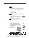
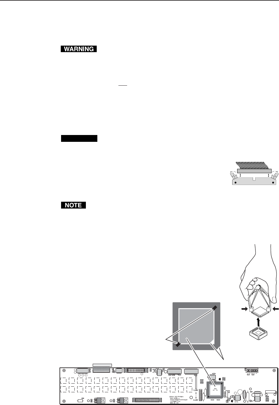
4. On the front panel board, press the two receptacle tabs
on the top cable outward as shown at the right, and pull
back gently on the cable connector to remove it from the
receptacle.
5. Lay the front panel down in front of the switcher.
The reach of the remaining cables connected to the front panel board on
CrossPoint Plus and CrossPoint 1616 and 168 switchers is just barely long
enough. Slightly lift the front of the switcher and slide the panel under the
switcher as you tip it away from the switcher.
Replace the Firmware IC
Replace the firmware IC as follows:
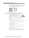
1. Locate IC U7 (figure 2) on the front panel board.
2. Use a PLCC IC puller to remove the existing firmware IC.
Squeeze the tool to align its
hooks with the slots in opposite
corners of socket U7. Insert the
hooks, squeeze gently, and pull
the IC straight out of the socket.
Discard the IC.
Ribbon cable
Connector
Self-latching receptacle
Slots for Removing IC
with PLCC IC Puller
Label includes
Extron part number &
Firmware version (Vx.xx).
Key
nnn
19-nnn-01
Vx.xx
Figure 2 — Location of IC U7 on the front panel board