


MLC 104 Series MediaLink Controllers • Hardware Setup
Hardware Setup
MLC 104 Series MediaLink Controllers • Hardware Setup
2-32-2
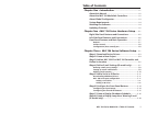
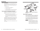
This chapter describes right, left, and front panel features, basic
front panel operation, and how to connect cables to the
MLC 104 series controller.
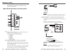
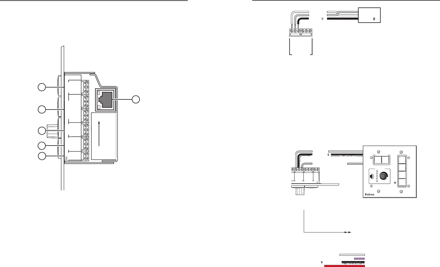
Right Side Panel Features and Connections
+V
G
SCP
+12V OUT
PWR SNS
GROUND
GROUND
GROUND
GROUND
GROUND
Tx
Rx
HOST/
CONFIG
LAN
PRESS TAB WITH
TWEEKER TO REMOVE
A B
A B E
MLS PWR
RS-232 12V
SCP
COMM
DISPLAY
RS-232/IR
Tx/IR
Rx
Tx
Rx
+12V IN
3
2
1
6
Right Side
MLC 104 Series
Right Side Panel
4
5
a
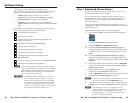
Right panel, Host/Config port — For MLC configuration and
control, connect to the 3-pin captive screw.
This port has the following RS-232 protocol:
• 38400 baud
• 1 stop bit
• no parity
• 8 data bits
• no flow control
b
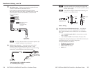
Display RS-232 /IR port — This port is configurable for
bidirectional RS-232 or infrared signal output control.
From this port, commands sent from a driver or user-defined
command strings (entered via the Global Configurator) can be
sent to the display device.
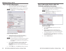
For bidirectional RS-232 communication, the transmit, ground,
and receive pins must be wired at both the controller and the
projector connectors, as shown on the following page.
Projector
Panel
MLC 104 Series
Right Side Panel
DISPLAY
RS-232/IR
Tx/IR
Rx
GROUND
PWR SNS
GROUND
+12V OUT
Ground ( )
Receive (Rx)
Transmit (Tx)
Ground ( )
Receive (Rx)
Transmit (Tx)
Bidirectional
N
Each projector or display may require different wiring. For
details, refer to the manual that came with your projector.
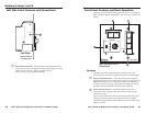
c
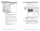
SCP Comm port — The SCP 104 replicates the MLC’s front
panel controls. You can connect up to two Extron SCP 104
control pads to this port to allow remote control of the MLC 104
controller.
SCPs can be daisy chained. Extron recommends the
Comm-Link (CTL and CTLP) cable for these connections.
+V
G
SCP
+12V OUT
GROUND
GROUND
A B
A B E
MLS PWR
RS-232 12V
SCP
COMM
Tx
Rx
+12V IN
MLC 104 Series
Right Side Panel
E
B
A
SCP communication (IR)
Ground ( )
+12 VDC
Maximum =
2 SCPs
Per System
Ground ( ) & Drain Wire
E
C
B
A
SCP Communication
Control Module Communication
+12 VDC
= White
= Black & Drain Wire
= Violet
= Red
SCP 104
CONFIG
DISPLAY
VOLUME
SCP 104
ON
PC
VCR
DVD
OFF
1
2
3
4
200' (61 m) max.
to Last Device
Extron CTLP Cable Color Code:
An MLC 104 series controller daisy chained to a
SCP 104
N
The maximum distance allowed between an MLC
controller and a SCP 104 is 200’ (61 m).