


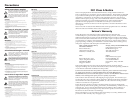
MediaLink VersaTools Switchers • Installation
MediaLink VersaTools Switchers • Installation
Installation, cont’d
Control and power connections
11
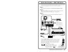
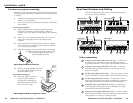
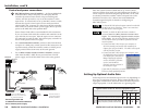
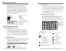
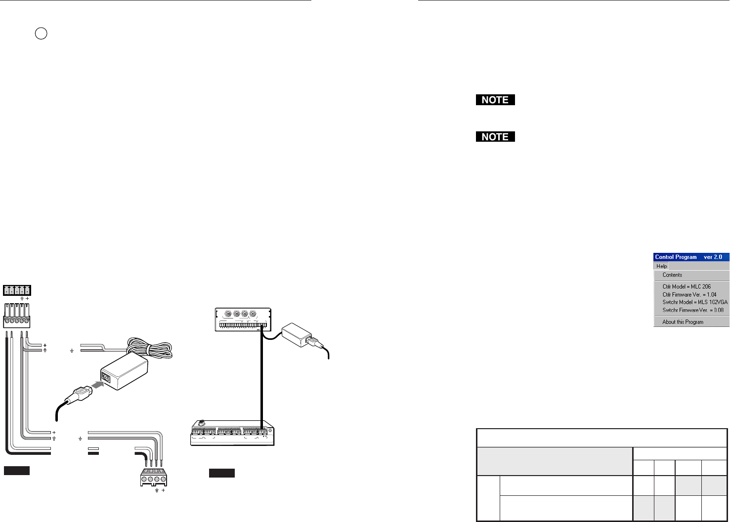
MLC/RS-232 Power port (all models) — An Extron MediaLink
Controller (MLC 206), a computer, or a third party RS-232
controller provides remote control of input switching and
volume, and also provides a way to set the switcher’s audio
input levels. To control and/or set up the MLS, connect a cable
between this 5-pole 3.5 mm captive screw connector and an
optional MLC 206, computer, or a third party RS-232 controller.
Also connect an external 12VDC power supply here to provide
power to the MLS and to the optional MLC.
Extron Comm-Link cable is recommended for this connection.
If you use Comm-Link cable, the switcher and controller can be
up to 250 feet (76.2 m) apart. Wire the captive screw connector
for connection to either an MLC 206 or third party controller as
shown in the picture on the next page.
• For a stand-alone MLS switcher, connect a cable from the host
computer or a third party control system to this connector to set
up and remotely control the switcher, connect a 12VDC power
supply, and tie all the drain wires to the same ground.
• For an MLS switcher slaved to an MLC controller, connect a
cable from the MLC’s MLS/Power port and from a 12VDC
power supply, and tie all the drain wires to the same ground.
MLC/RS-232
POWER
AB
MLS100Series
Switcher
MLC/RS-232
Power Port
ABCDEABC
IR
Display/Source Control
Extron Switcher Control
Relays IR/ RCM
RS-232
DE ABC ABD
1A 1B2A 2B 3A3B
123456
Tally Out
MLS
/Power
33-644-01 A
07 01
Printed in the
USA
MLC 206 Bottom Panel
MLS 103 V
Rear Panel
3
1
2
OUTPUT
INPUTS
MLS 103 V
LR
A
B
LR
LR
LR
1
2
3
LR
4
AUX/MIX
MONO
AUDIO INPUTS
OUT
CONTROL/
POWER
12V .5A MAX
Ground ( )
+12VDC input
+12VDC
Ground ( )
Transmit (Tx)
B
Receive (Rx)
A
Transmit (Tx)
Receive (Rx)
B
A
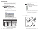
Connecting an MLC 206
to a MediaLink
VersaTools Switcher
and an external power supply
NOTE
You must connect a
ground wire between
the MLC and MLS.
MLC 206's
MLS/Power
Port
NOTE If you use cable that has a
drain wire, tie the drain wire
to ground at both ends.
AB
MLS
/
Power
Ground all devices
External
Power Supply
(12VDC, 1A max.)
External
Power Supply
250 ft
(76.2 m)
max.
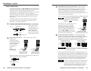
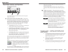
Setting Up Optimal Audio Gain
Audio input levels and desired output levels vary depending on
the types of equipment involved. Before setting the MLS’s per-
input gain or attenuation, determine the levels of the input and
output equipment. Use the table below as a general guide.
Typical Audio Levels for Various Equipment Types
Input/Output Levels
XX
Professional line level audio equipment
XX
+4dBu 0dBu
-10dBV
(-8dBu)
-20dBV
(-18dBu)
Equipment
Categories
Consumer audio equipment (VCRs, DVDs,
laptop computers, portable audio devices)
Once the system has been cabled and set up via the control
software and the front panel Aux/Mix adjustment, the MLC or
a host computer communicating through the MLC can be used
to remotely control the switcher. Refer to chapter four of the
MediaLink Controllers User’s Manual and to the MediaLink
Control Program help file for details on configuring an
MLC-MLS system.
An Extron IR Link infrared repeater cannot be used with
the MLS 100 Series switchers. There is no connection
for that device’s control signals.
The MLC to which the MLS 100 Series switcher is
connected must have MLC firmware version 1.04 or
higher. The control/setup software must be version
2.0 or higher. Use one of the following methods to find
out the version levels of the MLC’s firmware and the
control software.
• Connect the MLC’s RS-232 port to a computer or
RS-232 controller, and send an SIS command (see
chapter four) of Q to the MLC. The MLC will respond
with its firmware version.
• Connect the MLC’s RS-232 port to a computer, start
the MediaLink control software
(see chapter four), and click on
Help to display the software
version, the MLC’s firmware
version, and the MLS’s
firmware version as shown in
the example at right.
If your MLS’s firmware is an earlier version, contact
Extron to obtain updated firmware.
2-92-8