


Operation and Setup, cont’d
MLS 304 Series, MLS 406 Series • Operation and Setup
3-8
PRELIMINARY
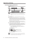
Remote Control
The MediaLink Switcher can be controlled by using its front panel controls; an
optional Extron infrared remote control (the MLA-Remote, for example) and an
Extron IR Link signal repeater; a MediaLink Controller; or another RS-232 control
device or computer. See Control Connection on page 2-7 for wiring diagrams and
system examples.
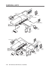
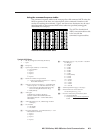
RS-232
MLC/IR
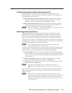
MediaLink Switcher to an MLC
MediaLink
Switcher
rear panel
RS-232/MLC/IR port
NOTE The switcher provides up to 12 VDC, 0.40 A power to an MLC 206.
Other MLC models may draw more current than the MLS can provide.
Extron recommends using a separate power supply for the MLC.
Ground ( )
+12 VDC input
NOTE If you use cable that has a
drain wire, tie the drain wire
to ground at both ends.
RS-232
MLC/IR
MediaLink Switcher to an MLC
that has an external power supply
MediaLink
Switcher
rear panel
RS-232/MLC/IR port
NOTE If using an external power
supply (instead of the MLS) to
power the MLC, you must
connect a ground wire
between the MLC and MLS.
NOTE If you use cable that has a
drain wire, tie the drain wire
to ground at both ends.
RS-232_MLC-IR port wiring_MLS304_062404.eps
RS-232
MLC/IR
TxRxIR
+
12V
TxRxIR
+
12 V
TxRxIR
+
12V
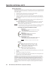
MediaLink Switcher to an IR Link
MediaLink
Switcher
rear panel
RS-232/MLC/IR port
IR Link
port
A B C
A B C
A B C
MediaLink Switcher Rear Panel
RS-232
MLC/IR
TxRx IR
+
12V
A B C
MediaLink Switcher Rear Panel
RS-232
MLC/IR
TxRx IR
+
12V
A B C
MediaLink Switcher Rear Panel
RS-232
MLC/IR
TxRxIR
+
12V
ABC
RS-232
MLC/IR
RS-232 port
of a
computer or
control system
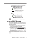
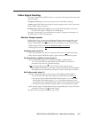
MediaLink Switcher to a
computer or control system
MediaLink
Switcher
rear panel
RS-232/MLC/IR port
NOTE Connect a ground wire
between the MLC and the
computer or control system.
NOTE If you use cable that has a
drain wire, tie the drain wire
to ground at both ends.
TxRxIR
+
12V
A B C
MediaLink Switcher Rear Panel
RS-232
MLC/IR
TxRx IR
+
12V
A B C
Host Computer Control System
or
Ground ( )
+12 VDC
Transmit (Tx)
B
Receive (Rx)
A
Ground ( )
Transmit (Tx)
B
Receive (Rx)
A
Ground ( )
Transmit (Tx)
B
Receive (Rx)
A
250 feet (76.2 m) maximum
150 feet (45.7 m) maximum
Ground ( )
+12 VDC
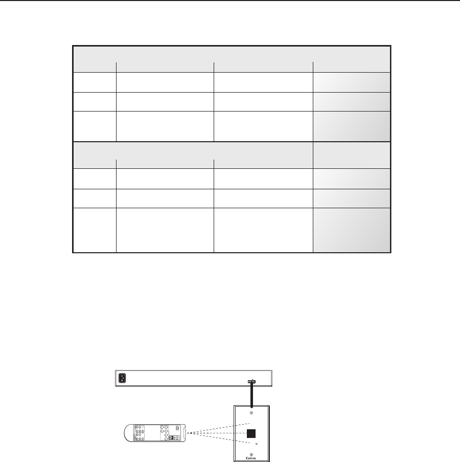
IR (IR Link)
C
IR Link
MLA-Remote
SIGNAL
IR
A B C D E
D
DVD
MLC
MLS/Power
port
MLC
MLS/Power
port
A B
MLS
/
Power
Transmit (Tx)
Receive (Rx)
+12 VDC
Ground ( )
B
A
A B
MLS
/
Power
Transmit (Tx)
Receive (Rx)
B
A
Transmit (Tx)
Receive (Rx)
3
2
Ground all devices
External
Power Supply
(12 VDC, 1A max.)
External
Power Supply
MediaLink
Controller
(MLC)
MediaLink
Controller
(MLC)
N Any Extron IR remote control that offers input selection buttons 1 through 6
can be used with the MLS switcher for input switching. Unlike most other
models, the MLA-Remote also allows volume control and audio mute.
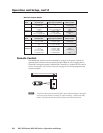
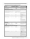
MLS 304MA, MLS 304SA
Mode Selected input Input special conditions Monitor Output
Standard Any composite video input n.a. None
Any RGB input n.a. Selected input
DA Any input 3 and 4 = RGB Input 4
Any input 3 or 4 = composite video None
RGB follow 1 or 2 3 and 4 = RGB Input 4
3 or 4 = RGB 3 and 4 = RGB Selected input
3 or 4 = composite video 3 or 4 = composite video None
MLS 406, MLS 406MA, MLS 406SA
Mode Selected input Input special conditions Monitor Output
Standard Any S-video or composite video n.a. None
4, 5, or 6 = RGB 4, 5, and 6 = RGB Selected input
DA Any 4, 5, and 6 = RGB Input 6
Any 4, 5, or 6 = S-video
or composite video None
RGB follow 1, 2, or 3 4, 5, and 6 = RGB Input 6
4, 5, or 6 = RGB 4, 5, and 6 = RGB Selected input
4, 5, or 6 = S-video 4, 5, or 6 = S-video
or composite video or composite video None
n.a. = not applicable
Monitor Output Modes