


Installation, cont’d
MLS 304 Series, MLS 406 Series • Installation
2-8
PRELIMINARY
RS-232
MLC/IR
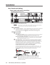
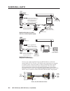
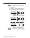
MediaLink Switcher to an MLC
MediaLink
Switcher
rear panel
RS-232/MLC/IR port
NOTE The switcher provides up to 12 VDC, 0.40 A power to an MLC 206.
Other MLC models may draw more current than the MLS can provide.
Extron recommends using a separate power supply for the MLC.
Ground ( )
+12 VDC input
NOTE If you use cable that has a
drain wire, tie the drain wire
to ground at both ends.
RS-232
MLC/IR
MediaLink Switcher to an MLC
that has an external power supply
MediaLink
Switcher
rear panel
RS-232/MLC/IR port
NOTE If using an external power
supply (instead of the MLS) to
power the MLC, you must
connect a ground wire
between the MLC and MLS.
NOTE If you use cable that has a
drain wire, tie the drain wire
to ground at both ends.
RS-232_MLC-IR port wiring_MLS304_062404.eps
RS-232
MLC/IR
TxRxIR +12V
TxRxIR
+12 V
TxRxIR
+12V
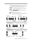
MediaLink Switcher to an IR Link
MediaLink
Switcher
rear panel
RS-232/MLC/IR port
IR Link
port
A B C
A B C
A B C
MediaLink Switcher Rear Panel
RS-232
MLC/IR
TxRx IR
+
12V
A B C
MediaLink Switcher Rear Panel
RS-232
MLC/IR
TxRx IR
+
12V
A B C
MediaLink Switcher Rear Panel
RS-232
MLC/IR
TxRxIR
+
12V
ABC
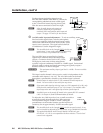
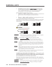
RS-232
MLC/IR
RS-232 port
of a
computer or
control system
MediaLink Switcher to a
computer or control system
MediaLink
Switcher
rear panel
RS-232/MLC/IR port
NOTE Connect a ground wire
between the MLC and the
computer or control system.
NOTE If you use cable that has a
drain wire, tie the drain wire
to ground at both ends.
TxRxIR +12V
A B C
MediaLink Switcher Rear Panel
RS-232
MLC/IR
TxRx IR
+
12V
A B C
Host Computer Control System
or
Ground ( )
+12 VDC
Transmit (Tx)
B
Receive (Rx)
A
Ground ( )
Transmit (Tx)
B
Receive (Rx)
A
Ground ( )
Transmit (Tx)
B
Receive (Rx)
A
250 feet (76.2 m) maximum
150 feet (45.7 m) maximum
Ground ( )
+12 VDC
IR (IR Link)
C
IR Link
MLA-Remote
SIGNAL
IR
A B C D E
D
DVD
MLC
MLS/Power
port
MLC
MLS/Power
port
A B
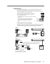
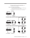
MLS
/
Power
Transmit (Tx)
Receive (Rx)
+12 VDC
Ground ( )
B
A
A B
MLS
/
Power
Transmit (Tx)
Receive (Rx)
B
A
Transmit (Tx)
Receive (Rx)
3
2
Ground all devices
External
Power Supply
(12 VDC, 1A max.)
External
Power Supply
MediaLink
Controller
(MLC)
MediaLink
Controller
(MLC)
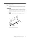
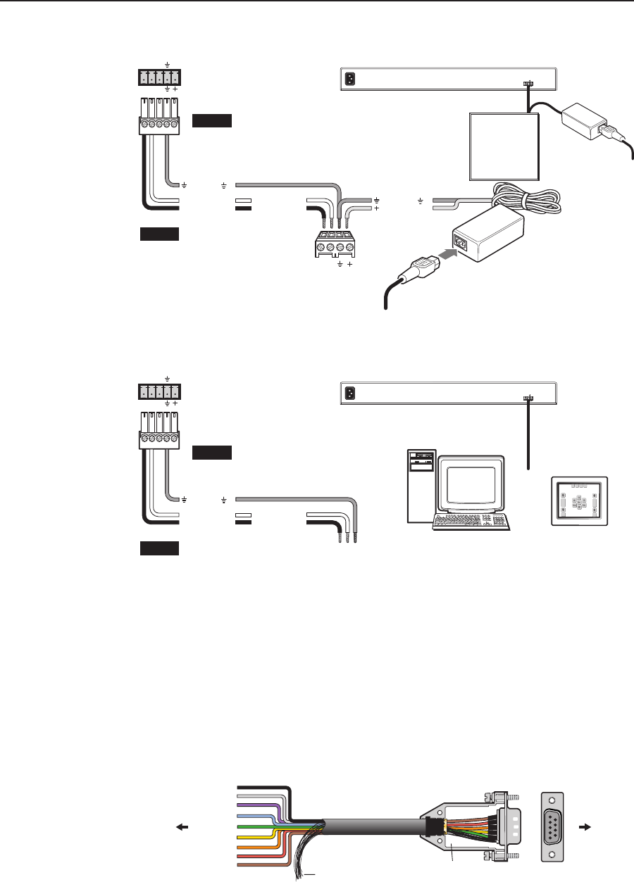
You may use a male 9-pin D-to-bare-wire RS-232 cable or a universal
control cable (UC 50', UC 100', or UC 200') for the connection to a computer
or control system. One end of the UC cable is terminated with a female
9-pin D connector, and the other end is unterminated. The UC cable’s
pin assignments are as shown in the following illustration. Refer to the
computer/control system’s pin assignment guide to determine which of the
cable’s wires to connect to which of the MLS’s RS-232/MLC/IR port pins.
1
5
9
6
7
6
5
4
3
2
1
8
9
Purple
Blue
Green
Yellow
Orange
Red
Brown
Grey
Black
Connector Shell
Pin #Color
UC Cable
Shield
UC 50', 100', 200' Cable Color Codes
To the
computer
or
control
system
To the
MLS
switcher