


2-9
MLS 304 Series, MLS 406 Series • Installation
PRELIMINARY
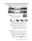
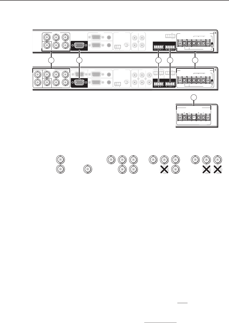
Video output, local monitor, and audio output connections
AUDIO INPUTS
LINE LEVEL
MONO
AUDIO
AUDIO
AUX/MIX
ADJUST
-42dB
TO
+24dB
L
R
L
R
1
2
INPUTSOUTPUTS
VIDEO
H
V
B
G
R
1
2
INPUTS
3
4
MONITOR OUT
100-240V
1.0A MAX.
50-60Hz
OUTPUTS
VIDEO
H
V
B
G
R
Y
MONITOR OUT
C
RL
AUDIO INPUTS
LINE LEVEL
MONO
AUDIO
AUDIO
AUX/MIX
ADJUST
-42dB
TO
+24dB
L
R
L
R
L
R
1
2
3
INPUTS
OUTPUTS
VIDEO
H
V
B
G
R
Y
1
2
3
INPUTS
MONITOR OUT
4
5
6
C
100-240V
1.0A MAX.
50-60Hz
RS-232/MLC/IR
Tx
Rx IR 12V
A B C
PREAMPLINEOUT
AUDIO INPUTS
LINE LEVEL
MONO
AUDIO
AUDIO
AUX/MIX
ADJUST
-42dB
TO
+24dB
L
R
L
R
1
2
OUTPUTS
VIDEO
H
V
B
G
R
3
4
MONITOR OUT
AUDIO INPUTS
AUDIO
AUDIO
L
R
L
R
L
R
1
2
3
INPUTS
4
5
6
LINE LEVEL
MONO
AUX/MIX
ADJUST
-42dB
TO
+24dB
INPUTS
AMPLIFIED OUTPUT
20 WATTS MONO
DIRECT
XFMR
COM
4/8 ohm
100V
70V
AMPLIFIED OUTPUT
20 WATTS MONO
DIRECT
XFMR
COM
4/8 ohm
100V
70V
4
RL RL
RS-232/MLC/IR
Tx
Rx IR 12V
A B C
PREAMPLINEOUT
RL RL
AMPLIFIED OUTPUT
4/8 ohm
RIGHT LEFT
STEREO OR DUAL MONO
CLASS 2 WIRING
RL
RS-232/MLC/IR
Tx
RxIR 12V
A B C
PREAMPLINEOUT
4
RL RL
RS-232/MLC/IR
Tx
RxIR 12V
A B C
PREAMPLINEOUT
RL RL
2 4 5
3a
3b
61
7 8 9 10 11
12
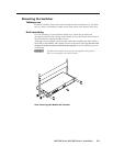
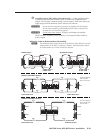
MLS 304MA and MLS 304 SA Rear Panel
MLS 406, MLS 406MA, and MLS 406SA Rear Panel
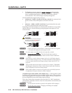
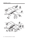
MLS 304MA Rear Panel
MLS 406MA Rear Panel
MLS 406SA Rear Panel
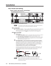
(amplifier output)
VIDEO
Y
C
H
V
B
G
R
H
V
B
G
R
H
V
B
G
R
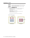
RGBHV RGBS RGsB, RsGsBs
S-video
(MLS 406 Series)
Composite
video
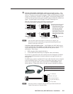
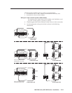
The output signal is in the same format (RGBHV, RGBS, RGsB, RsGsBs,
S-video, or composite video) as the input signal. The signal is switched,
but not processed. Cables can be connected between the projector and
one, some, or all of the switcher’s video outputs.
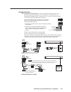
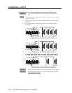
h
Monitor Output — This 15-pin HD connector serves as either a local
monitor loop-through port or an additional RGB output. Connect a cable
between this port and the local or additional display device.
There are three different options (modes) for determining which input
signal, if any, is sent to the monitor output. These modes are selectable
only via RS-232 control. For an explanation of modes and video routing,
see pages 3-7 and 3-8. See chapter 4, Serial Communication for details
on selecting the mode.
Audio outputs
Lineout audio output and Preamp audio output — These outputs are
simultaneously active and can be wired and configured for balanced or
unbalanced mono or stereo audio signal output. The switcher must also
be configured for the corresponding signal type (mono or stereo).
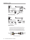
Selecting either mono or stereo (via RS-232 by way of the control software
or SIS commands) selects the output signal format for both the Lineout
and Preamp outputs. The switcher configuration (mono or stereo) and
the output wiring must match.
• The Lineout connector outputs a fixed, line level audio signal that is
not affected by front panel Volume knob adjustments. A recording
or assistive listening device would typically be connected here.
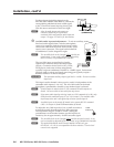
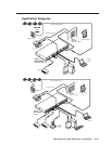
Video outputs
g
Display outputs — Connect cables from the
appropriate port(s) on the projector or display
panel to these BNC connectors according to the
output signal type, as shown below.