


2-7MediaLink Switchers • Installation
VIDEO
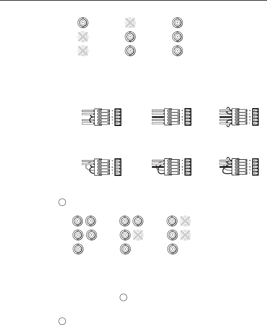
Y
C
R-Y
B-Y
VIDEO
Y
C
R-Y
B-Y
VIDEO
Y
C
R-Y
B-Y
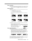
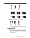
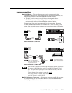
Component
video
(R-Y, Y, B-Y)
S-video
(Y, C)
Composite
video
Video input connections for MLC 506/506MA/506SA inputs 1–3
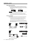
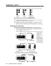
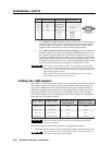
For audio input, wire the audio input connector as shown below.
LR
LR
LR
LR
LR
LR
Unbalanced Stereo Input
Tip
Sleeve
Tip
Sleeve
Balanced Stereo Input
Tip
Ring
Sleeve (s)
Tip
Ring
Tip
Ring
Sleeve (s)
Tip
Ring
Balanced Stereo Input
(high impedance)
(high impedance) (600 ohms)
600 ohms
600 ohms
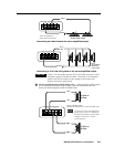
Unbalanced Mono Input
Tip
Sleeve
Tip
Sleeve
Balanced Mono Input
Tip
Ring
Sleeve (s)
Tip
Ring
Tip
Ring
Sleeve (s)
Tip
Ring
Balanced Mono Input
(high impedance)
(high impedance) (600 ohms)
600 ohms
3
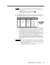
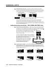
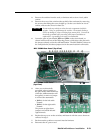
Inputs 4–6 — For inputs 4, 5, and 6, connect a computer to the
appropriate BNC connectors for RGB computer video input.
RGBHV
(separate
H & V sync)
RGBS
(composite
sync)
RGsB/RsGsBs
(sync on green; or
sync on red, green, & blue)
RH/
HV
G
V
B
RH/
HV
G V
B
R H/
HV
G V
B
Connect each input’s stereo audio source to the 3.5 mm, 5-pole captive screw
connector for balanced or unbalanced input. Wire the audio input connectors
as shown above in
2
.
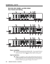
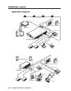
Video output connections
4
RGB computer video output — Connect coaxial cables from these five BNC
connectors to the projector for computer video output from inputs 4–6. Cable
the BNC connectors according to the signal format as shown in the following
illustration. The output signal will be in the same format (RGBHV, RGBS,
RGsB, RsGsBs) as the input signal. The signal is switched, but not processed.
Cables can be connected between the projector and one, some, or all of the
switcher’s video outputs.