


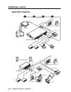
Installation, cont’d
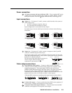
MediaLink Switchers • Installation2-10
EFFECTS
LR
SEND
LR
RETURN
Left
Right
Gnd ( )
Right
Left
Gnd ( )
Audio Processing
Device
11
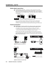
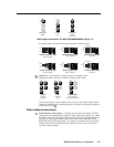
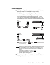
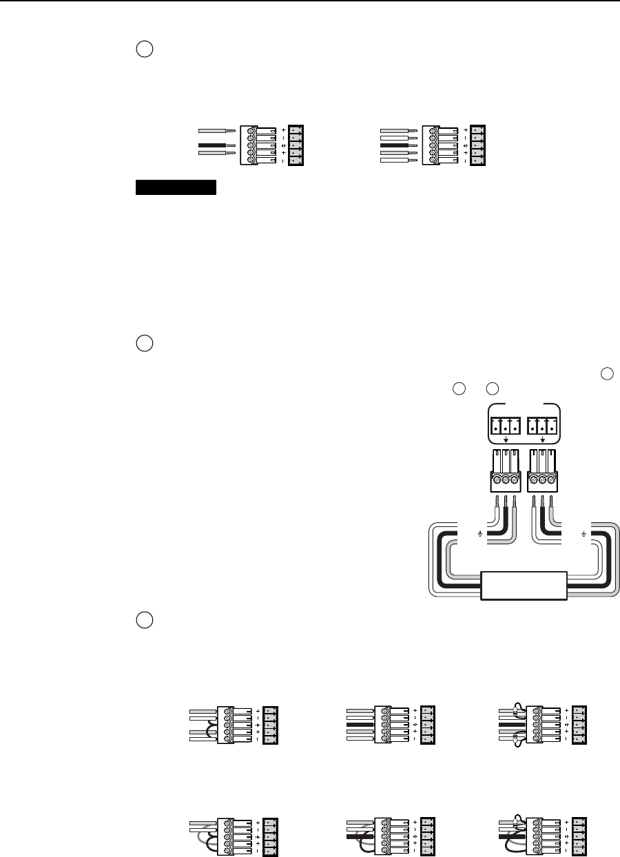
Audio Out(put) connectors — Connect an audio output device to either
connector for balanced or unbalanced audio output. A device such as a tape
recorder can be connected to the Fixed output while speakers can be connected
to the Variable output. Wire each captive screw connector as shown below.
Unbalanced Output
Tip
See Caution
Sleeve (s)
Tip
See Caution
Balanced Output
Tip
Ring
Sleeve (s)
Tip
Ring
LR
AUDIO OUT
AUDIO OUT
LR
CAUTION
Connect the sleeve to ground (Gnd). Connecting the sleeve to a negative
(-) terminal will damage the audio output circuits.
The Fixed connector outputs audio at a fixed level and is unaffected by
changes made via the front panel Volume/Adjust knob. The Variable
connector outputs audio that can be attenuated by turning the Volume knob.
These preamp outputs can be set for mono or stereo output via the front panel
menu or the control software.
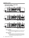
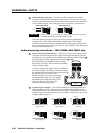
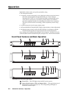
Audio processing connections — MLS 506MA, MLS 506SA only
9
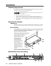
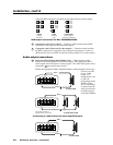
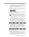
Effects connectors (Send, Return) — These two 3.5 mm, 3-pole captive screw
connectors allow the selected audio signal to be looped through an optional
recording device or equalizer before being sent to the main Audio Output (
11
)
(preamp outputs) or the amplified audio output (
7
or
8
).
We recommend using shielded cables no longer
than 10 feet (3 meters). These connectors should be
wired as shown at right.
An active, unbalanced signal is always available at
the Send connector. The Return connector accepts
the unbalanced signal that has been routed through
an external device. In order for the
Return connector to accept an incoming/
returning audio signal, you must enable
the Return port via the front panel LCD
menu (see pages 3-5 and 3-6) or the
Windows-based setup program.
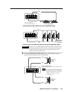
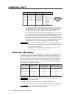
10
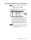
Aux/Mix input connector — An auxiliary balanced or unbalanced line level
audio signal input at this connector can be mixed with the signal from the
selected audio input. Use the front panel Mix knob to control the level of this
auxiliary signal. Wire the connector as shown below, which is the same as the
wiring for audio inputs 1–6.
LR
LR
LR
LR
LR
LR
Unbalanced Stereo Input
Tip
Sleeve
Tip
Sleeve
Balanced Stereo Input
Tip
Ring
Sleeve (s)
Tip
Ring
Tip
Ring
Sleeve (s)
Tip
Ring
Balanced Stereo Input
(high impedance)
(high impedance) (600 ohms)
600 ohms
600 ohms
Unbalanced Mono Input
Tip
Sleeve
Tip
Sleeve
Balanced Mono Input
Tip
Ring
Sleeve (s)
Tip
Ring
Tip
Ring
Sleeve (s)
Tip
Ring
Balanced Mono Input
(high impedance)
(high impedance) (600 ohms)
600 ohms