


1
This guide describes how to connect the Extron MMX 32 architec-
tural adapter plate (AAP) or MMX 32 mini architectural adapter plate
(MAAP) to the MMX 32 VGA A and MMX 32 VGA MTP matrix switchers.
In this manual, the term “switcher” refers to either the
MMX 32 VGA A or the MMX 32 VGA MTP. Where differences
exist, this manual refers to a specifi c model by name.
Contact Closure Control
Each Extron MMX 32 AAP and MMX 32 MAAP remote control panel
selects the input for one switcher output via contact closure.
The contact closure system uses the pins on the switcher’s Remote
connector(s) that are not assigned to RS-232 control. Each contact
closure pin corresponds to an input/output connection, or tie. A tie is
made when one pin is connected to ground.
Each pin returns a tally out signal to the remote control panel after a tie
is made, lighting the control panel LED corresponding to the selected in-
put. Power to light the LEDs is provided via the switcher’s Tally Power
(MMX 32 VGA A) or +5V (MMX 32 VGA MTP) connector(s).
The MMX 32 VGA MTP uses a separate 5-pin captive screw
connector for contact closure input selection for output 1 and
for output 2. The pin assignments are clearly marked on the
MMX 32 VGA MTP.
The MMX 32 VGA A uses a DB-9 connector for the connections
(see MMX 32 VGA A pin assignments below).
MMX 32 VGA A pin assignments
The table below shows the contact closure pin assignments for the
MMX 32 VGA A.
For contact closure do not use pins 2 or 3.
Pin RS-232Contact closure noitcnuF
Out #1 / In #1
2TX
11
Transmit data
3 Receive data
Out #1 / In #2
5 Gnd Gnd Signal ground
Out #1 / In #3
Out #2 / In #1
Out #2 / In #2
Out #2 / In #3
Tie input 1 to output 1
Tie input 1 to output 2
Tie input 2 to output 2
Tie input 3 to output 2
Tie input 3 to output 1
Tie input 2 to output 1
—
RX—
—
4
—
6
—
7
—
8
—
9
—
5
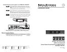
1
9
6
TALLY
PWR
5V
MMX 32 VGA A Remote and Tally Power connectors
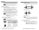
Control Panel Connections
To connect a panel to the switcher’s Remote and Tally Power connectors,
wire the captive screw connectors on the rear of the panel as follows.
2
4
3
1
5
MMX 32 AAP rear panel
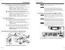
4
2
3
5
1
MMX 32 MAAP rear panel
The wire connected to the 5 VDC pole (
4
) should not be daisy
chained. The power for each AAP or MAAP must come directly
from the Tally Power 5V connector on the MMX 32 VGA A
switcher or the +5V connector for the appropriate output on the
MMX 32 VGA MTP switcher.
Input selection connector
1
Input 1 pole — Connect this pole of the captive screw connector
to the appropriate connector on the connected switcher:
• MMX 32 VGA A — Remote connector, pin 1 (to control input
selection for output 1) or pin 7 (for output 2)
• MMX 32 VGA MTP — Contact 1 pin 1 (to control input
selection for output 1) or Contact 2 pin 1 (for output 2)
1 MMX 32 AAP and MMX 32 MAAP • Installation Guide
Installation
2
MMX 32 AAP and MMX 32 MAAP • Installation Guide