


Connection
43
Connection
2
Input 2 pole — Connect this pole of the captive screw connector
to the appropriate connector on the connected switcher:
• MMX 32 VGA A — Remote connector, pin 4 (to control input
selection for output 1) or pin 8 (for output 2)
• MMX 32 VGA MTP — Contact 1 pin 2 (to control input
selection for output 1) or Contact 2 pin 2 (for output 2)
3
Input 3 pole — Connect this pole of the captive screw connector
to the appropriate connector on the connected switcher:
• MMX 32 VGA A — Remote connector, pin 6 (to control input
selection for output 1) or pin 9 (for output 2)
• MMX 32 VGA MTP — Contact 1 pin 3 (to control input
selection for output 1) or Contact 2 pin 3 (for output 2)
Tally Power Connector
4
5 VDC pole — Connect this pole of the captive screw connector to
the appropriate connector on the connected switcher:
• MMX 32 VGA A — Tally Power connector, 5V pole
• MMX 32 VGA MTP — Contact connector, +5V pole for the
appropriate output.
5
Ground pole — Connect this pole of the captive screw connector
to the appropriate connector on the connected switcher:
• MMX 32 VGA A — Tally Power connector, ground pole
• MMX 32 VGA MTP — Contact connector, ground pole for
the appropriate output.
Connecting the Control Panel to the Switcher
L
R
I
N
P
U
T
2
I
N
P
U
T
1
A
U
D
I
O
A
U
D
I
O
O
U
T
P
U
T
1
A
U
D
I
O
I
N
P
U
T
3
A
U
D
I
O
R
E
M
O
T
E
A
U
D
I
O
R
S
-
2
3
2
+
5
V
P
O
W
E
R
1
2
V
0
.
5
A
M
A
X
2
1
1
2
3
CONTACT
T
x
R
x
SYNC - TRI
PRE PEAK - ON
O
U
T
P
U
T
2
R
G
B
/
A
U
D
I
O
Extron
AAP 102 w/
MMX AAP
Extron
MMX 32 MTP
Matrix Switcher
Laptop
Podium
Computer
Control
Extron
STP 22 Dual Plenum
Cable 22-162-03
Document
Camera
LCD Monitor
with Audio
Projector
Audio System
1
I
N
P
U
T
S
E
L
E
C
T
2
3
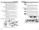
Typical MMX 32 VGA MTP / control panel application
Only one MMX 32 AAP or MMX 32 MAAP control panel can
be used to control each output.
Extron recommends shielded twisted pair cable, such as
STP 22 Dual Plenum cable, part #22-162-03 (or equivalent),
for the connection between the control panel and the switcher.
Unshielded cable can allow crosstalk and interference between the
MMX and the control panel.
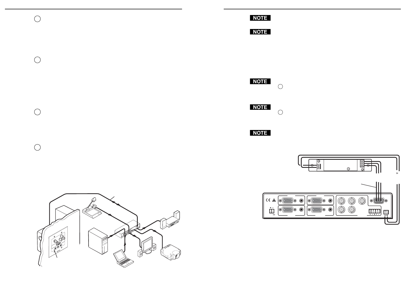
Connecting the control panel to an MMX 32 VGA A
See the drawing below. The wire connected to the 5 VDC pole
(
4
on pages 2 and 3) should not be daisy chained. The power
for each AAP or MAAP must come directly from the Tally Power
connector on the MMX switcher.
See the drawing below. The wire connected to the Ground pole
(
5
on pages 2 and 3) should not be shared or jumpered between
two AAPs and/or MAAPs. Run a separate ground wire for each
AAP and/or MAAP. Use the drain wire of the cable for ground.
The drawing below shows a control panel wired to select the input
tied to MMX 32 VGA A output 2, using pins 7, 8, and 9 on the
Remote connector. To select the input tied to output 1, use pins 1,
4, and 6 on the Remote connector.
LR
POWER
12V
.5A MAX
INPUT 2
INPUT 1
AUDIO
AUDIO
OUTPUT 1 OUTPUT 2
INPUT 3
R
H
GB
V
AUDIO
REMOTE
AUDIO
TALLY
OUT
5V
MMX 32 VGA A
MMX 32 AAP
Red +5V
Extron
STP 22 Dual Plenum
Cable 22-162-03
White
Green
Black
Ground ( )
Pins 7, 8, and 9
Wiring diagram for a typical MMX 32 VGA A application