


MMX 42/62 Series Matrix Switchers • Installation
MMX 42/62 Series Matrix Switchers • Installation
Installation, cont’d
Video signal output connections
4
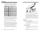
Composite video output connectors — Connect composite
video displays to these two female BNC connectors.
5
S-video output connectors — Connect S-video displays to these
two 4-pin mini DIN connectors.
Audio signal input connections
6
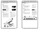
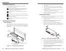
3.5 mm, 5-pole captive screw connectors — Connect balanced
and unbalanced stereo audio inputs to these sockets using
connectors which are included with each MMX SVA switcher
(you must supply the audio cable). See figure 2-8 for an
illustration on how to wire a connector for the appropriate input
type and impedance level.
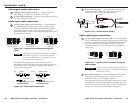
Figure 2-8 — Captive screw connector wiring for
input
When making connections for the switcher from existing
audio cables, see figure 2-9. A mono audio connector
consists of the tip and sleeve. A stereo audio connector
consists of the tip, ring and sleeve.
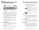
The audio level for each input can be individually set, via
RS-232 link, to ensure that the level on the output does not vary
from input to input. See chapter 3, Operation, and chapter 4,
Remote Control, for details.
Figure 2-9 — Phono audio connectors
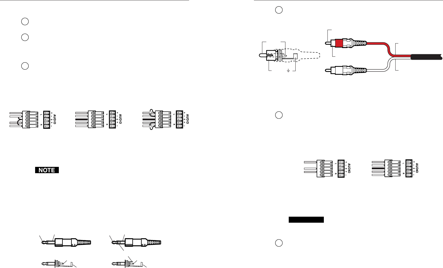
7
RCA audio connectors — Connect unbalanced stereo audio
inputs to these RCA connectors. See figure 2-10 for an
illustration on how to wire the RCA connector.
Figure 2-10 — RCA connector wiring
Audio signal output connections
8
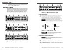
3.5 mm, 5-pole captive screw connectors — Connect balanced
and/or unbalanced stereo audio outputs to these sockets using
connectors which are included with each MMX SVA switcher
(you must supply the audio cable). See figure 2-11 for an
illustration on how to wire a connector for the appropriate
output type.
Figure 2-11 — Captive screw connector wiring for
audio output
CAUTION
Connect the sleeve to ground (Gnd). Connecting
the sleeve to a negative (-) terminal will damage the
audio output circuits.
9
RCA audio connectors — Connect unbalanced stereo audio
outputs to these RCA connectors. See figure 2-10 for an
illustration on how to wire the RCA connector.
By default, the audio output follows the video switch. Audio
breakaway, commanded via the RS-232 link, allows the user to
select from any one of the audio input sources. See chapter 4,
Remote Control for details on the RS-232 connection.
2-6 2-7
Tip (L) Sleeve (Gnd)
Tip (L)
Ring (R)
Sleeve (Gnd)
Tip Sleeve
Unbalanced mono Unbalanced stereo
Tip (signal)
Sleeve (Gnd)
Unbalanced Input
Tip
Sleeve
Tip
Sleeve
Balanced Input
Tip
Ring
Sleeve (s)
Tip
Ring
Tip
Ring
Sleeve (s)
Tip
Ring
Balanced Input
(high impedance)
(high impedance) (600 ohms)
600 ohms
600 ohms
Unbalanced Output
Tip
See Caution
Sleeve
Tip
See Caution
Balanced Output
Tip
Ring
Sleeve (s)
Tip
Ring
Tip (+)
Sleeve ( )
Sleeve (Gnd )
Right Channel
(Red Jacket)
Left Channel
(White Jacket)
Tip (Signal)