


MMX 42/62 Series Matrix Switchers • Remote Control
MMX 42/62 Series Matrix Switchers • Remote Control
Remote Control, cont’d
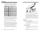
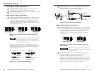
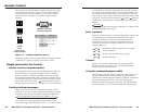
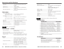
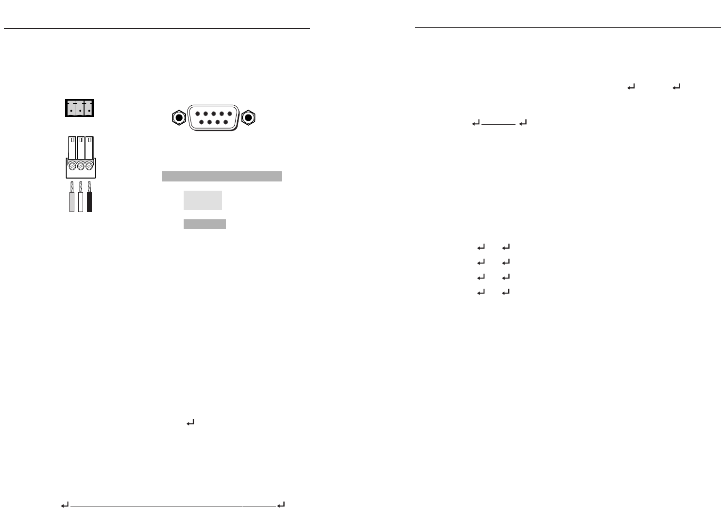
The switcher’s rear panel Remote connector (figure 4-1) can be
connected to the serial port output of a host device. Remote
communications with the switcher are via Extron’s Simple
Instruction Set or using Extron’s Windows-based control
program.
Figure 4-1 — Remote connector pinout
The RS-232 protocol of the rear panel RS-232/Remote connector
is 9600 baud, 1 stop bit, no parity, and no flow control.
Simple Instruction Set Control
Host-to-interface communications
SIS commands consist of one or more characters per field. No
special characters are required to begin or end a command
character sequence. When a command is valid, the switcher
executes the command and sends a response to the host device.
All responses from the switcher to the host end with a carriage
return and a line feed (CR/LF = ), which signals the end of
the response character string. A string is one or more characters.
Switcher-initiated messages
When a local event, such as a front panel operation or error
condition, occurs, the switcher responds by sending a message
to the host. The switcher-initiated messages are listed below:
(C) Copyright 2003, Extron Electronics MMX xx, Vx.xx
The switcher issues the copyright message and the input
selected message when it first powers on. Vx.xx is the firmware
version number. Outy Inn All identifies the currently selected
ties, where y is the output number, n is the input number, and
All is both video and audio (the power-up default is video and
audio output 1 tied to input 1 and video and audio output 2 tied
to input 2). The switcher also sends the
Outy Inn message
whenever the selected input is changed using the front panel
buttons.
Reconfig
The switcher initiates this message when there is a change in the
audio gain setting for any input.
Error responses
When the switcher receives a valid SIS command, it executes the
command and sends a response to the host device. If the
switcher is unable to execute the command because the
command is invalid or it contains invalid parameters, the
switcher returns an error response to the host. The error
response codes are:
E01 - Invalid input channel number (out of range)
E10 - Invalid command
E12 Invalid output number (out of range)
E13 - Invalid parameter
Timeout
Pauses of 10 seconds or longer between command ASCII
characters result in a timeout. The command operation is
aborted with no other indication.
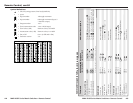
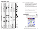
Using the command/response table
The command/response table is on the next page. Lower case
letters are allowed in the command field only as indicated.
Symbols are used throughout the table to represent variables in
the command/response fields. Command and response
examples are shown throughout the table. The ASCII to HEX
conversion table is for use with the command/response table.
4-34-2
Remote Control
DB9 Pinout (Female)
To control equipment
51
96
Rx
Tx
Gnd
Rx
Tx
Gnd
RS-232
3-pole
captive screw
connector/socket
Pin RS-232 Function
1—
2 TX Transmit data (-)
3 RX Receive data (+)
4—
5 Gnd Signal ground
6—
7— —
8— —
9— —
—
—
—