


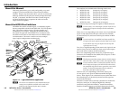
Refer also to the MTPX Plus User’s Manual at www.extron.com.
Refer also to the MTPX Plus User’s Manual at www.extron.com.
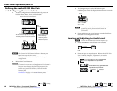
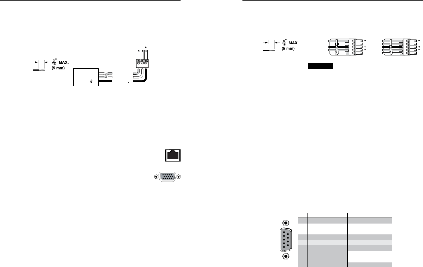
RS-232 output inserts
e
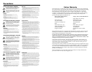
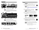
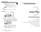
RS-232 Output Insert connectors — For bidirectional RS-232
data that is routed to a specific (unswitchable) TP output,
connect a serial device to one of the RS-232 Output Insert 3-pole
captive screw connectors.
Receive (Rx)
Transmit (Tx)
Ground ( )
Bidirectional
RS-232
Device
Ground ( )
Receive (Rx)
Transmit (Tx)
RxTx
Do not tin
the wires!
Figure 2-5 — RS-232 output inserts connector wiring
N
Each RS-232 Output Insert must be enabled. See the
"RS-232 output inserts enables" SIS commands on
page 4-5.
N
The switch time for the RS-232 output insert is 50 ms.
Outputs
f
TP outputs — Connect up to 8, 16, or 32 (depending
on the matrix size) compatible MTP receivers to the
Outputs RJ-45 connectors.
g
Local RGB (VGA) outputs — Connect one or two
RGBHV video displays to the female Local
Outputs (VGA) 15-pin HD connectors.
N
Matrix sizes 1616 and smaller (excluding the
MTPX Plus 128) have one local video output.
Matrix sizes 1632 and larger and the MTPX Plus 128
have two local video outputs.
N
The Local outputs are always outputs 1 and 2.
N
The video that is output on these connectors is converted
from the tied proprietary TP input signal or the local
(VGA) input.
N
This connector can also output HD component video,
component video, S-video, or composite video if that is the
video format that was input.
If the video output is NTSC component video, S-video, or
composite video, set the output to no sync processing. See
the "Local video output sync polarity" SIS commands on
page 4-9.
h
Local audio outputs — Connect audio devices, such as audio
amplifiers or powered speakers to these two, four, or eight
3.5 mm, Mono Audio (local audio) Outputs 5-pole captive screw
connectors to receive unamplified, mono line level audio.
Unbalanced Output Balanced Output
L R
Ring
Tip
Sleeve(s)
Tip
Ring
Sleeve(s)
Tip
Tip
NO GROUND HERE.
NO GROUND HERE.
Do not tin
the wires!
CAUTION For unbalanced audio, connect the sleeve
to the gr
ound contact. DO NOT connect
the sleeve to the negative (-) contacts.
Figure 2-6 — Audio output connector wiring
N
The MTPX Plus 128 has two local audio outputs.
Matrix sizes 1616 and smaller have four local audio
outputs.
Matrix sizes 1632 and larger have eight local audio
outputs.
N
These outputs are always outputs 1 and 2 (MTPX Plus 128),
outputs 1 through 4 (matrix sizes up to 1616) or outputs
1 through 8 (matrix sizes 1632 and larger), with the same
inputs tied to them as the TP output of the same number.
N
Each local output has a volume control. See "Viewing and
Adjusting the Audio Level" on page 3-7.
Remote control
i
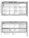
Remote port (switchers other than the MTPX Plus 128) — If
desired, connect a control system or computer to the rear panel
Remote RS-232/RS-422 port.
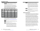
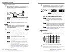
RS-232 Function Pin Function
1
2
3
4
5
6
7
8
9
—
TX
RX
—
Gnd
—
—
—
—
Not used
Transmit
Receive
Not used
Ground
Not used
Not used
Not used
Not used
—
TX–
RX–
—
Gnd
—
RX+
TX+
—
Not used
Transmit (–)
Receive (–)
Not used
Ground
Not used
Receive (+)
Transmit (+)
Not used
RS-422
5
1
9
6
Figure 2-7 — Remote port connector wiring
j
Remote (RS-232) connector (MTPX Plus 128) — A 3-pin captive
screw connector for serial RS-232 control (figure 2-5)
MTPX Plus Series • Installation
Installation, cont’d
2-4
MTPX Plus Series • Installation
2-5