


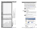
Refer also to the MTPX Plus User’s Manual at www.extron.com.
Refer also to the MTPX Plus User’s Manual at www.extron.com.
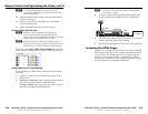
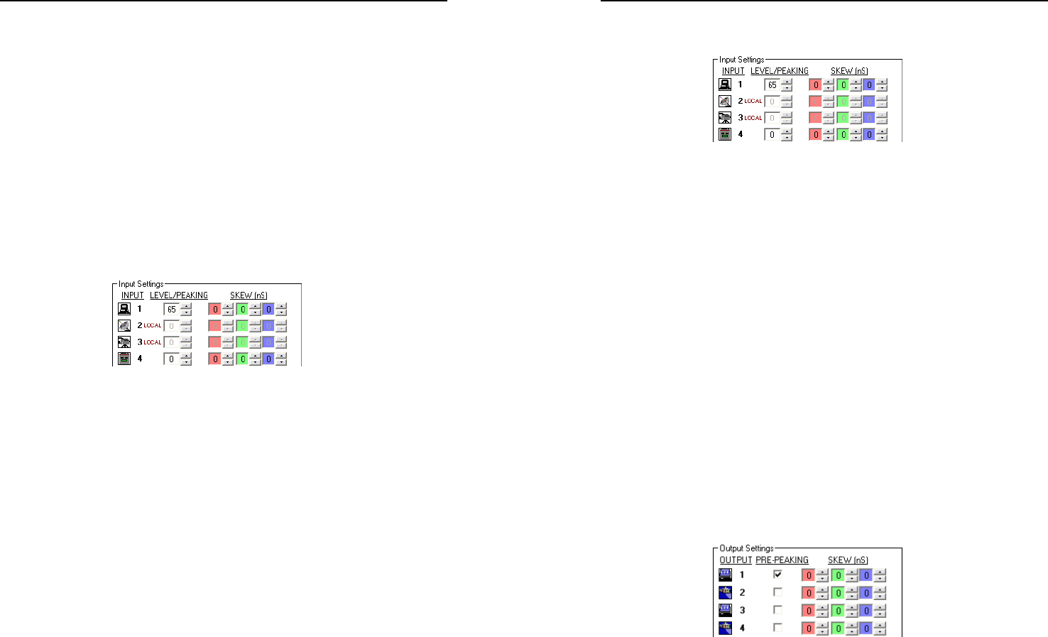
Manually setting the MTPX level and peaking
If you choose not to auto calibrate, or if you want to fine tune
the adjustment, you can manually set the values as follows:
1. Connect an oscilloscope (preferred) or a monitor
(acceptable) to local output (VGA output) 1.
2. If using an oscilloscope, apply a white field test pattern to
the input to be optimized via an MTP transmitter.
If using a monitor, apply a grayscale or Color Bars
test pattern to the input to be optimized via an MTP
transmitter.
H
The Extron VTG 300 or VTG 400 are recommended to
provide the test pattern.
3. Tie the input to be optimized to output 1.
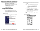
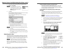
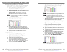
4. Click Tools > MTPX Picture settings.
5. Observe the oscilloscope or the monitor with a critical
eye while you adjust the input level/peaking setting to
compensate for signal loss between the transmitter and the
MTPX.
6. If necessary, repeat steps 1 through 5 for each input.
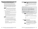
Setting MTPX skew
1
. Connect an oscilloscope (preferred) or a monitor
(acceptable) to local output (VGA output) 1.
2. Apply a crosshatch test pattern to the input to be
optimized via an MTP transmitter.
3. Tie the input to be optimized to output 1.
4. Use the test equipment or examine the displayed video
image with a critical eye to determine which video
signal — red, green, or blue — is most shifted to the left.
5. If necessary, click Tools > MTPX Picture settings.
6
. Adjust the skew setting of the leftmost video signal to the
right until all three colors are properly converged.
N
When the skew adjustment is set to zero, the MTPX Plus
cannot shift the rightmost video image to the left.
N
A 2-nanosecond adjustment is very fine. Up to 10
nanoseconds of delay may be necessary before you detect a
change in the display.
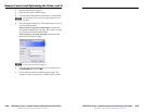
6. Adjust the skew setting of the leftmost video signal to the
right until all three colors are properly converged.
7. If either of the two remaining colors is left shifted, repeat
steps 4 and 6.
8. Repeat steps 2 through 7 for all other inputs.
9. Connect an oscilloscope (preferred) or a monitor
(acceptable) to the MTPX twisted pair output to be
adjusted, via an MTP receiver.
10. Apply a crosshatch test pattern to one of the local (VGA)
inputs on the MTPX Plus.
11. Tie the local input receiving the test pattern signal to the
output to be optimized.
12. Use the test equipment or examine the displayed video
image with a critical eye to determine which video
signal — red, green, or blue — is most shifted to the left.
13. If necessary, click Tools > MTPX Picture settings.
N
When the skew adjustment is set to zero, the MTPX Plus
cannot shift the rightmost video image to the left.
MTPX Plus Series • Remote Control and Optimizing the Video
Remote Control and Optimizing the Video, cont’d
4-20
MTPX Plus Series • Remote Control and Optimizing the Video
4-21