


RGB 190F, RGB 192 and RGB 198 • Installation and Operation
RGB 190F, RGB 192 and RGB 198 • Installation and Operation
Installation and Operation, cont’d
2-8 2-9
options, such as serration pulse and video termination
changes, have been tried.
On — The interface uses DDSP, which does not process
the sync signal.
DDSP disables the horizontal and vertical centering
controls.
Off — The interface performs sync processing operations.
5 — No monitor (ID bit termination) — This switch controls
the input assigned to the local monitor output and ID bit
termination.
On — ID bits 4 and 11 are tied to ground.
Off — ID bits 4 and 11 are unterminated.
6 — Mono audio output (RGB 192 only, spare on RGB 190F)
On — Monaural audio is output on the left channel only.
When mono is selected, the right and left inputs
are combined and placed on the left output
connectors.
Off — Normal stereo output.
7
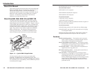
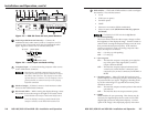
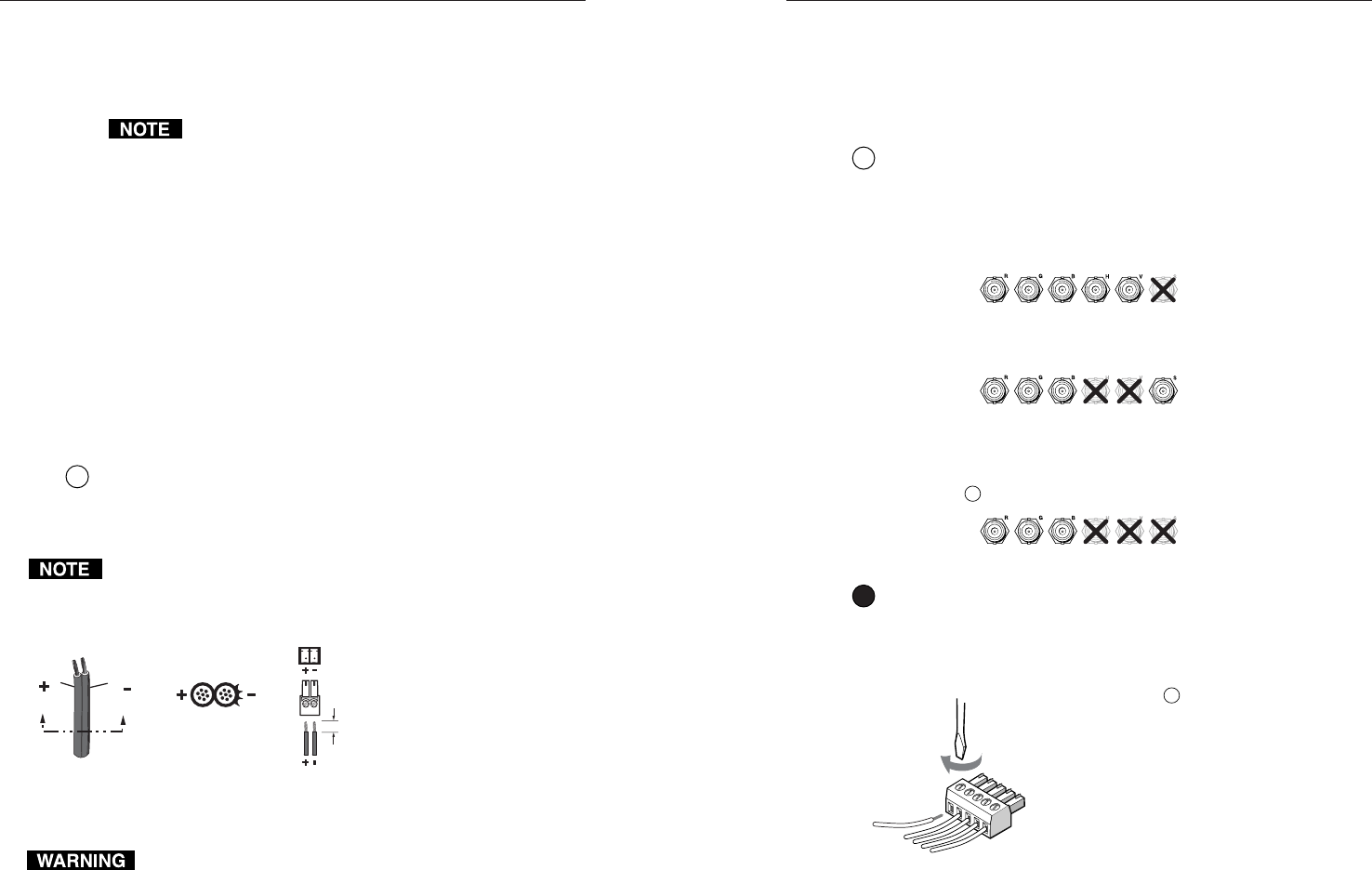
Power connector — Plug the external 12V power supply into
this 2-pole captive screw connector. The power supply is
included with the unit. Figure 2-7 shows how to wire the
connector.
Do not tin the stripped power supply leads before installing the
captive screw connector. Tinned wires are not as secure in the
captive screw connectors and could pull out.
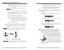
Power Supply
Output Cord
Captive Screw
Connector
0.2” (5 mm) MAX
SECTION A–A
Ridges
Smooth
AA
Figure 2-7 — Power connector wiring
The two power cord wires must be kept separate while the power
supply is plugged in. Remove power before continuing.
To verify the polarity before connection, check the no-load
power supply output with a voltmeter.
Alternatively, an Extron P/S 100 Universal 12VDC Power
Supply can power up to six RGB 190F or RGB 192
interfaces using only one AC power connector.
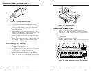
8
BNC output connectors — Connect a coaxial cable between the
display (projector or monitor) and these rear panel BNC
connectors.
For RGBHV (separate H and V sync) output, connect the cables
to five BNCs.
RGBHV
For RGBS (composite sync), connect the cables to four BNCs.
RGBS
For RGsB (sync on green, SOG), connect the cables to three
BNCs. Also select the SOG option on the front panel DIP switch
(see item
6
, Dip switches, in this chapter.
RGsB
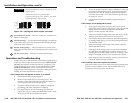
9
Stereo audio output connector (RGB 192 and 198 only) —
Connect an audio device, such as powered speakers, to this
3.5mm, 5-pole captive screw connector for balanced or
unbalanced stereo or mono audio output. Stereo or mono
output is determined by a DIP switch setting on the front panel.
See DIP switch 6 in item
6
, DIP switches, on the
previous page. When mono is selected, the right
and left inputs are combined and placed on the left
output connectors. Balanced or unbalanced
outputs are available for mono and stereo.
The illustration here shows how to wire
the captive screw audio connector. The
connector is included with the interface, but
you must obtain the cable. Insert the wires into the appropriate
openings in the captive screw connector. Tighten the screws on
top to fasten the wires.