


RGB 190F, RGB 192 and RGB 198 • Installation and Operation
RGB 190F, RGB 192 and RGB 198 • Installation and Operation
Installation and Operation, cont’d
2-10
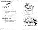
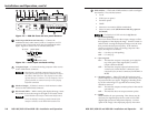
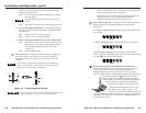
CAUTION
Wiring the audio incorrectly can damage the audio
output circuits.
Connect the sleeve(s) to ground (GND).
Connecting the sleeve(s) to a negative (-) terminal
will damage audio output circuits.
L/
Mono
L/
Mono
R
R
Unbalanced Output
Tip
See caution
Sleeve
Tip
See caution
Balanced Output
Tip
Ring
Sleeve (s)
Tip
Ring
Figure 2-8 — Wiring the audio output connector
10
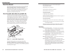
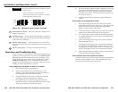
Unswitched AC outlets —These AC outlets are available in an
Edison or Euro plug.
11
MAAP openings — Two double MAAP openings, one adjacent
to the other, allow up to four single-sized MAAP pass through
audio and video connectors.
12
Double AAP openings — This plate allows easy access to the
back of the MAAPs while safely isolating the power supply and
interface.
13
IEC AC power plug — Provides convenient power input.
Operation and Troubleshooting
Connect the power cords and turn on the displays (projectors or
monitors), audio output devices (sound system) (RGB 192 and
198 only), the interface and the input device (computer). The
image should appear on screen, and sound should be audible
(RGB 192 and 198 only). If not, ensure that all devices are
plugged in and receiving power. Check the cabling and switch
settings, and make adjustments as needed.
If the image does not appear or there is no sound
1. Ensure that all devices are plugged in.
2. Make sure that each device is receiving power. The
interface’s front panel LED lights green if the interface is
receiving power and an active sync signal.
3. Check the cabling and the audio connector wiring and
grounding, and make adjustments as needed.
4. For digital display devices (including LCD, DLP and
plasma devices), try turning the DDSP DIP switch (switch
4) On (up) or Off (down) on the front panel.
5. To test the system setup and output, substitute a video test
generator for the computer input. Unplug the input and
output devices’ and the interface’s power cords, replace
the video source with a VTG, then reconnect power cords
to restore AC power.
6. Call the Extron S
3
Sales & Technical Support Hotline if
needed.
If the image is not displayed correctly
• If the output image looks too green, the sync on green
(SOG) DIP switch (switch 2) may be set to On (up), and the
display device may not be configured to handle SOG
signals. Set the switch to Off (down).
• If the picture bends or flags at the top of the screen, set the
serration pulse DIP switch (switch 3) to Off (down).
• For a display device that experiences intermittent glitches,
try turning DDSP On (up) or Off (down) using DIP switch
1 on the front panel.
• If the picture hangs off the edge of the screen, adjust the
Horizontal Shift control.
• If the edges of the image seem to exceed their boundaries
or if thin lines and sharp edges look thick and fuzzy, try
changing the Level DIP switch (switch 1) to On (up). If the
image is too bright, turn the Level switch to Off (down).
• If the image still does not display correctly, call the Extron
S
3
Sales & Technical Support Hotline.
If the interface does not respond to controls
If the picture does not move on screen when the horizontal shift
control is rotated, DDSP is in use. Set the DDSP DIP switch
(switch 4) on the front panel to Off (down).
2-11