


RGB 324/326/340 • Installation and Operation
RGB 324/326/340 • Installation and Operation
Installation and Operation, cont’d
Pre-installation testing/troubleshooting
Before installing a buffer into the wall or furniture, test the
system to make sure that the connections and settings are
correct.
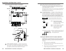
1. With the power disconnected from the RGB 320, connect
the cables between the buffer and the RGB 320 as
described in “Preparing and terminating the cable” in this
chapter.
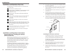
2. Apply power to the RGB 320. The power LED on the
buffer will light steadily to indicate that the buffer is
receiving power.
• If the power LED does not light, check the captive
screw connector wiring at both the buffer and the
RGB 320. If the conductor assignments are not the
same at both ends, the buffer will not turn on, and
circuits may be damaged if power is applied to the
wrong pole.
If the image does not appear or there is no sound
1. Make sure that the RGB 320 and the buffer are powered on
(see above), and that the source computer connected to the
buffer is powered on.
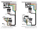
2. Verify that the connectors are wired identically at both
ends of the cable connecting the buffer to the RGB 320.
Ensure that the audio portion is wired correctly for the
input signal (balanced or unbalanced).
3. Verify that the front panel High Z/75 ohm video input
termination switch has been set correctly.
• The switch should be set to High Z if a local monitor
is connected, a laptop breakout cable is used, or the
picture is too dark (double-terminated).
4. Select that buffer as the active input to the RGB 320.
• The RGB 326 buffer must be selected via the RGB 320
front panel or an RS-232 control device. The Active
LED on the front panel of the RGB 326 will light
when that buffer is selected as the active input.
• The RGB 324 and RGB 340 can be selected via the
RGB 320 front panel or an RS-232 control device, or
by pressing the Show Me/Select button on the buffer.
If the Show Me/Select button blinks, the RGB 320 is
busy, and the Show Me/Select button must be
pressed a second time.
5. Call the Extron S3 hotline if the image still does not appear
or there is no sound.
2-16 2-17
If the image is not displayed correctly
1. If the picture looks too green, the computer may be
sending video with sync on green (SOG), and the display
device may not be configured to handle SOG signals. The
buffers do not strip sync from the video input signals.
2. If the picture “hangs off” the edges of the screen, adjust the
horizontal centering and/or vertical centering (RGB 324
and RGB 340 only). See page 2-6 for details.
3. If the picture is too bright or too dark, try changing the
front panel High Z/75 ohm termination switch (all buffer
models, see page 2-5), adjust the level/peaking jumpers
(all models, see page 2-9), or adjust the video level
(RGB 324/RGB 340 only, see page 2-6).
4. If the edges of the image seem to exceed their boundaries,
or if thin lines and sharp edges look thick and fuzzy,
change the level/peaking jumper settings. See page 2-9.
5. If the picture appears and is stable, but it has ghosting or
blooming, try changing the High Z/75 ohm video input
termination (see page 2-5). If the problem is not resolved
by changing the termination, try using a different input
cable.
6. If the picture still is not displayed correctly, call the Extron
customer support hotline.
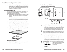
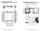
Mounting the buffer to the wall box
(RGB 324, RGB 326)
Once the system has been cabled and tested, the buffer can be
installed in the wall or furniture.
1. Remove power from the RGB 320 by disconnecting the
power cord.
2. Detach the input cables from the buffer’s front panel.
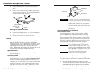
3. Place the buffer through the opening in the wall or
furniture and into the wall box (if one is used).
4. Mount the buffer’s faceplate to the wall box with the
provided machine screws as shown in the illustration on
the next page, or attach the buffer directly to the furniture
with wood or metal screws.