


RGB 324/326/340 • Installation and Operation
RGB 324/326/340 • Installation and Operation
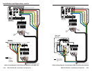
Installation and Operation, cont’d
2-6 2-7
5
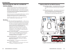
Adjust knob (RGB 324, RGB 340) — Turning this knob adjusts
the horizontal centering, vertical centering, video level, or audio
level of the active buffer.
After the RGB 320 switches inputs, wait for the
projected picture and the horizontal and vertical scan
rates on the RGB 320’s LCD panel to stabilize before
making adjustments. Adjustments made before the
system stabilizes may not be stored in memory.
To make adjustments, follow these steps:
1. While the buffer is active (the Show Me/Select button/
LED is lit), press the Show Me/Select button. The H Shift
LED lights to indicate that horizontal centering can now be
adjusted.
2. Rotate the Adjust knob while viewing the displayed image
to select the desired horizontal position of the picture.
3. Press the Show Me/Select button to activate the vertical
centering adjustment. The V Shift LED lights.
4. Rotate the Adjust knob while viewing the displayed image
to select the desired vertical position of the picture.
5. Press the Show Me/Select button to activate the video
level adjustment. The Video Level LED lights.
6. Rotate the Adjust knob while viewing the displayed image
to select the picture brightness.
7. Press the Show Me/Select button to activate the audio
level adjustment. The Audio Level LED lights.
8. Rotate the Adjust knob while listening to the audio output
to select the appropriate audio level.
9. Press the Show Me/Select button again or wait 7.5 seconds
to exit the adjustment mode.
When an adjustment reaches a minimum or maximum
limit, the buffer’s adjustment indicator (
7
) LED blinks.
The RGB 320’s LCD display indicates the adjustments
that are being made from the buffer.
The buffer has priority over the RGB 320 and the
RS-232 control device in terms of making adjustments.
Adjustments to a buffer’s settings from the RGB 320 or
the RS-232 control cannot take place while an
adjustment is being made from the buffer itself.
6
Show Me/Select button (RGB 324, RGB 340) — Press this
button once to request the RGB 320 to send the signal from this
buffer to the display/projector. If the request is granted, the
buffer’s Show Me/Select button (RGB 324) or the LED next to
the Show Me/Select button (RGB 340) lights. The LED
corresponding to the input from this buffer will light
on the RGB 320.
If the RGB 320 is busy, the buffer’s Power LED will
blink, and the Show Me/Select button must be pressed
again to send the request.
Press the Show Me/Select button twice in succession to enter
the adjustment mode. In adjustment mode you can make
adjustments to centering and to audio and video levels by
rotating the buffer’s Adjust knob.
7
Adjustment indicator LEDs – H Shift, V Shift, Video Level,
Audio Level (RGB 324, RGB 340) — Each of these LEDs lights
when that adjustment is selected. See
5
above.
8
Active LED (RGB 326) — This LED lights to indicate that the
buffer has been selected (via the RGB 320’s front panel or an
RS-232 control device), and it is providing the input to the
display/projector.