


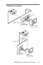

RGB 460xi Series • Installation and Operation
2-9
N
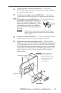
If the signal cable between the interface and the output
device is shorter than approximately 125 feet, and
the gain switch is set to Medium or Maximum, the
image may be overcompensated. If the edges of the
image seem to exceed their boundaries, or if thin lines
and sharp edges look thick and fuzzy, try changing
the gain/peaking setting. The gain switch will not be
accessible after installation, so adjust the gain before
placing the interface into a wall or furniture.
d
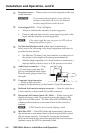
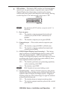
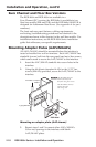
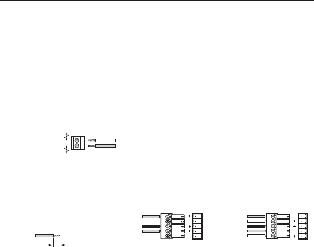
Power connector — Connect a 9 VDC to 24 VDC power supply
to this 3.5 mm, 2-pole, direct insertion
captive screw connector. Wire the connector
as shown here. Polarity is not important.
e
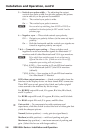
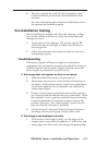
Audio output connector — Insert wires into and tighten the
screws on this 3.5 mm, 5-pole, direct insertion captive screw
connector for unbalanced or balanced audio output. Wire the
connector as shown here.
0.2” (5 mm) max.
Do not tin the wires!
Tip
Ring
Tip
Ring
Tip
Sleeve(s)
Tip
Unbalanced
Stereo Output
NO GROUND HERE.
NO GROUND HERE.
Balanced
Stereo Output
L R
L R
C For unbalanced audio, connect the sleeve(s) to the
ground (_) contact. DO NOT connect the sleeve(s) to
the negative (-) contacts.
N Items f, g, h, and i are 464xi interface only.
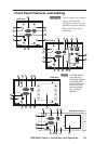
f
Composite video pass-through BNC connector — A male BNC
connector attaches here.
g
S-video pass-through 4-pin mini DIN connector — A male
4-pin mini DIN connector attaches here.
h
Balanced active audio output connector — Insert wires into
and tighten the screws on this 3.5 mm, 5-pole, direct insertion
captive screw connector for balanced active audio output. Wire
the connector as shown above.
i
Network pass-through RJ-45 connector — If this connector is
not required, a blank cover is supplied to ll the opening.
+ or –
– or +
9-24VDC
Power