


SW USB Series • Installation
Installation, cont’d
2-12
SW USB Series • Installation
2-13
PC
Host Port
SW USB Extron
A/V Switcher
2
3
5
RX
RX
TX TX
TX
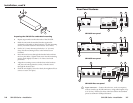
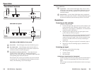
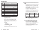
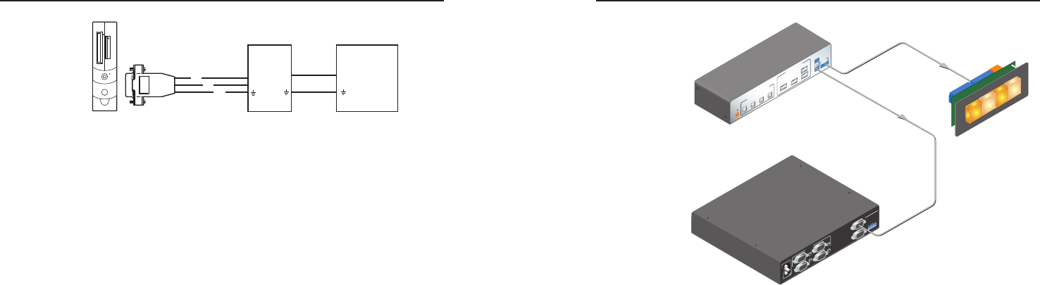
Connections for RS-232 loop-through
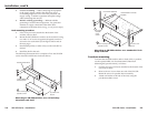
Contact Closure Control
Contact closure provides another method of input selection.
To enable input selection by contact closure, you can connect a
push-button contact closure device (such as Extron’s CCR 2BLB,
CCR 4BLB, or CCR 204) to the SW USB’s Contact port.
Alternatively, you can manually short one of the pins to ground
(the ground [_] pin is pin 3 for SW2 and pin 5 for SW4 models).
Pin 1 selects input 1, pin 2 selects input 2, etc.
Controlling an Extron A/V switcher in Loop 0 mode
For applications in which the SW USB is connected to an Extron
A/V switcher that can be controlled via RS-232, input selection
on both switchers can be done by contact closure (as well as
by the SW USB front panel buttons and the RS-232 interface).
To select inputs on the A/V switcher via contact closure, the
SW USB must be in Loop 0 mode (in other words, the SIS
command
E
LOOP0
} has been issued)
.
If the SW USB is in Loop 0 mode and an Extron A/V switcher
is connected to the RS-232 Pass Thru port, an input selection
command issued via contact closure selects the same input on
both the SW USB and the connected switcher.
USB SWITCHING INPUT
Tx
Tx Rx
RS-232
CONTACT
1
2
3
4
RS-232
PASS THRU
USB OUTPUT HUB
USB 3
USB 1
PC 1
PC 2
PC 3
PC 4
USB 2
USB 4
1.5A MAX
12V
POWER
+
100-240V 0.2A
50-60Hz
REMOTE
INPUTS
1
2
3
4
OUTPUT
OUTPUT
L
R
SW6 VGA Ars
Extron
SW4 USB
USB Switcher
RS-232 Loop Out
Contact Closure
Extron
CCR 4BLB
Controller Module
Extron
SW4 VGA Ars
VGA/Audio Switcher
1
2
3
4
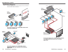
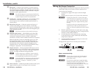
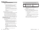
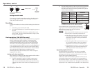
Using the SW USB with a contact closure device and
an A/V switcher
To congure the SW USB for contact closure control of an A/V
switcher,
1. If desired, connect a contact closure device to the SW USB’s
Contact port.
2. Connect the SW USB’s RS-232 Pass Thru port to the A/V
switcher’s RS-232 port.
3. Issue the SIS command
E
0LOOP} to the SW USB to
enable Loop 0 mode.
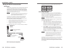
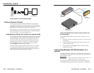
Connecting Multiple SW USB Switchers in a
System
The USB specication states that a maximum of ve hubs can be
connected in a series; therefore, no more than ve SW USBs can
be cascaded in a series.
C
Do not exceed five cascaded hubs and a total of 127
peripheral devices in the entire system.
The diagram on the next page shows an example of SW USBs
and peripheral output devices daisy-chained from a single host.