


2
SM 26 • Setup Guide (Continued)
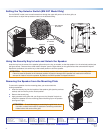
NOTE: A speaker wire access hole (see the following figures) must also be cut in the wall. Mark that hole location now
with the mounting plate positioned on the wall while ensuring that the wall stud does not interfere with the wire routing
and that the mounting plate hides the access hole.
3. Drill the mounting plate pilot holes and cut the speaker wire access hole, as previously marked.
4. Install the speaker cables into the wall before installing the speaker mounting plate. Leave enough slack in the cable.
5. Install the mounting plate.
NOTE: Since applications can vary considerably, it is assumed that the installer will exercise good judgment when
selecting the mounting location, method, and hardware. Mounting hardware is not provided.
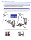
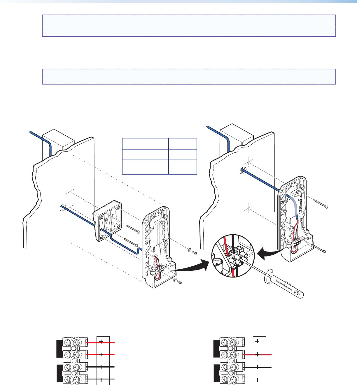
z If using the 10° mounting adapter, route the speaker cable through the adapter and 0° mounting plate, attach the adapter
to the 0° mounting plate using the four included screws and washers, then attach the wire ends to the quick connect
contacts using a small screwdriver. Be sure to observe the correct polarity. Attach the mounting plate to the wall (see the
figure below).
z If using only the flat plate, route the speaker cable through the rear of the mounting plate and attach the wire ends to the
quick connect contacts using a small screwdriver. Be sure to observe the correct polarity, as shown below. Attach the
mounting plate to the wall (see the figure above).
10° Mounting
Adapter
0° Mounting Plate
(4) 4-40 x 3/16"
Screws
Quick Connect Contacts
Mounting Scr
ews
Red Wire (+) from Amplifier
Black Wire (-) from Amplifier
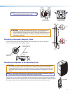
Red Wire (+) from
Amplifier/Previous Speaker
Red Wire (+) to Next Speaker
Black Wire (-) from
Amplifier/Previous Speaker
Black Wire (-) to Next Speaker
LOOPIN INLOOP
LOOPIN INLOOP
Loop-through Connection Single Speaker Connection
Number of Wires
per Connection Point
Maximum
Wire Gauge
1 12 AWG
2 16 AWG
4 18 AWG
Wire Gauge Table