


VSC 700/900 SDI Output Card • Installation
Installation
2
Installing the SDI Ouput Card
The SDI output card may be installed in the VSC 700/900 by
following the instructions and illustrations shown below.
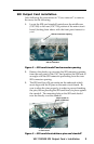
Cover removal
1. Remove the power cable from the VSC and from the power
source.
Do not open the cover of the scan converter without
unplugging the power cord.
2. If the VSC scan converter is rack mounted, detach the input
and output cables from it and remove the unit from the
rack. If the VSC is not rack mounted, you do not need to
remove the input and output cables.
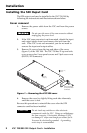
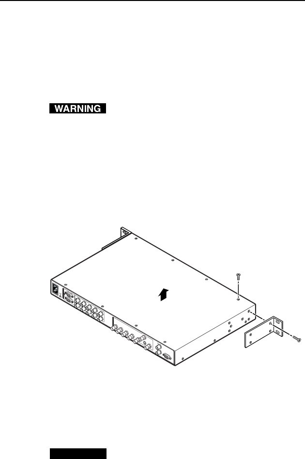
3. Remove 14 screws from the top and sides of the cover
(figure 1) of the VSC 900. The VSC 700 has 12 top and side
cover screws plus 9 rear panel screws and 2 jack screw nuts
(RS-232/422 connector).
5
0
/
6
0
H
z
1
0
0
-2
4
0
V
0
.3
A
R
/R
-
Y
R
/R
-
Y
I
N
P
U
T
S
O
U
T
P
U
T
S
G
/Y
2
R
G
B
/R
-
Y
, Y
,
B
-Y
R
G
B
1
G
/Y
B
/B
-Y
B
/B
-
Y
H
/H
V
H
/H
V
V
V
V
ID
E
O
S
-
V
I
D
E
O
D
1
R
/
R
-
Y
G
/Y
B
/B
-Y
H
/
H
-
Y
R
S
-
2
3
2
/
4
2
2
G
E
N
L
O
C
K
V
I
N
O
U
T
Remove #8 Screw
(4 Plcs) Each Side
and Bracket
Remove (14)
Screws
Lift Cover
straight up
Figure 1 — Removing the VSC 900 cover
4. Remove the cover by slightly lifting each side alternately
until the cover is free.
Reverse this procedure to reinstall the cover after the SDI
connector card has been installed.
CAUTION
Do not touch any switches or other electronic
components inside the VSC. Doing so could damage
the scan converter. Electrostatic discharge (ESD)
can damage IC chips even though you cannot feel it.
You must be electrically grounded. A grounding
wrist strap is recommended.