


VSC 700/900 SDI Output Card • Installation 3
SDI Output Card installation
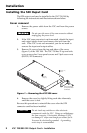
After following the instructions in “Cover removal” to remove
the cover, do the following:
1. Locate the SDI card standoff located near the middle rear
(VSC 900) or left rear (VSC 700) portion of the main circuit
board (looking from above with the front panel nearest to
you).
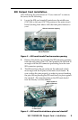
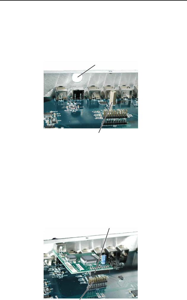
SDI card standoff
SDI card connector opening
Figure 2 — SDI card standoff and connector opening
2. Remove the plastic cap covering the SDI connector opening
from the rear panel of the VSC, and position the SDI card at
an angle with the SDI connector protruding from the rear
SDI connector opening.
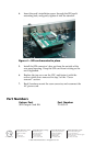
3. The SDI card has a 20-pin socket on the underside which
must align with the 20 pins on the main circuit board. Be
sure to align the pins properly, in order to prevent bending
the pins, before pressing the SDI card firmly in place against
the standoff. The mounting hole on the SDI card should
now be directly over the standoff.
20-pin socket on
back of SDI card
20-pin connector
on main board
Figure 3 — SDI card situated above pins and standoff