


Extron • VTG 150 & VTG 200 • User’s ManualExtron • VTG 150 & VTG 200 • User’s Manual
Operating the Video Test Generator
Page 3-2
Exit the Instructional Menu Cycle
To exit the instructional menu cycle, press the
▼▼
▼▼
▼ or
▲ ▲
▲ ▲
▲ button.
A scan range will be displayed on the LCD screen.
View the Scan Ranges
To view the available scan ranges (i.e. TTL, VGA, Mac), hold
the MODE/ON button down and press the
▼▼
▼▼
▼ or
▲▲
▲▲
▲ button. The
LCD will display a different scan range each time the button
is pressed. Stop when the desired scan range is displayed by
the LCD.
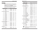
_ There are several scan rates within each scan range. If the
desired scan range is unknown, the tables in chapter 4 may be
helpful. However, be aware that an updated VTG may offer
scan rates that are not listed in the tables. Stepping through
the scan ranges and scan rates on the VTG device will show
all available scan formats.
View the Scan Rates
Press either the
▼ ▼
▼ ▼
▼ or
▲▲
▲▲
▲ button to step through the scan rates
(i.e. CGA, Mac II, XGA). Continuously pressing the
▼▼
▼▼
▼ or
▲▲
▲▲
▲
button will step through all scan rates of all scan ranges. To
change to a different scan range while viewing the scan
rates, press and hold the MODE/ON button and press the
▼▼
▼▼
▼
or
▲ ▲
▲ ▲
▲ button.
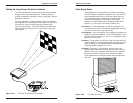
Activate a Scan Rate
Press the SELECT button when the desired scan rate
appears on the LCD readout. When the selection is made,
the Timer LED will turn green and a dot test pattern will
appear on the output screen of the device under test. This is
test pattern #1.
To return to the main menu after activating a scan rate
(cancel the scan rate), press the SELECT button.
Operating the Video Test Generator
Page 3-1
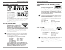
Operating the Video Test Generator
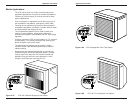
Connect the video test generator to the device to be tested.
(See Connecting the VTG Output Cables in chapter 2.)
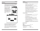
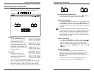
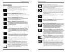
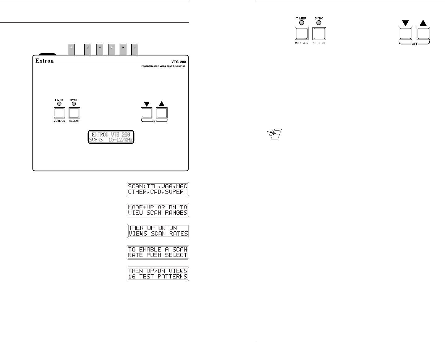
Power On
Press the MODE/ON button to
turn VTG power On. The LCD
display cycles through six
instructional menus (Main Menu)
that tell how to operate the video
test generator. The first is the
identification screen (shown in the
picture above). The other five are
shown to the right.
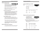
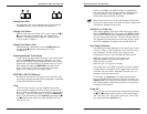
Timer LED
The color of the Timer LED
identifies the current operating
state of the VTG. The possible
Timer LED colors are:
• Off = VTG inactive (no scan rate selected)
• Green = VTG active (scan rate is selected), timer is running.
• Red = VTG active (scan rate is selected), timer is disabled.
• Blinking red & green = Time-out occurred, video is muted.
• Orange = VTG is in Auto-sequence mode, timer is disabled.