


Extron • VTG 150 & VTG 200 • User’s ManualExtron • VTG 150 & VTG 200 • User’s Manual
Host/VTG 200 Communications
The VTG 200 treats any character that it receives on the
RS-232 port as a possible command, but it accepts only a
limited number as legal commands. There are no codes
required to say that a command is coming or that a command
has ended. A simple command may be a single character
typed on a keyboard and does not require any special
characters before or after (it is not necessary to press “enter”
from the keyboard). Simple commands could be sent from a
terminal or any other controlling device.
When the VTG 200 receives a command and determines that
it is valid, it will execute the command and send a response
back to the controlling (host) device. If the command is
determined by the VTG 200 to be invalid, an error response
will be returned to the host. All responses from the VTG 200
to the host begin and end with a carriage return (CR). The
second CR signals the end of the response character string
(string = one or more characters).
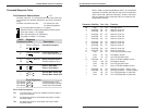
Using the Command/Response Table
The table on the following page lists those commands which
the VTG 200 recognizes as valid and the responses that will
be returned to the host. The description column defines the
command, the results of executing the command, or the
response returned to the host.
The command string in the left column of the table is defined
in the right column (both in bold print). The command string
is shown as ASCII characters.
VTG 200 RS-232 Control and Software
Page 5-2
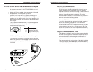
VTG 200 RS-232 Control and Connection to a Computer
A computer connected to the VTG 200 RS-232 port can be
used to:
• Add to the Extron supplied video scan formats in the field.
• Duplicate most VTG 200 panel operations.
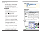
Each VTG 200 ships with a 3.5” diskette containing the
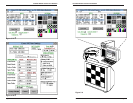
Extron Windows-compatible
VTG 200 Control Program
which
enables the user to perform all of the above operations in a
Windows environment. The program will be covered later in
this chapter.
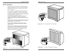
The VTG 200’s RS-232 port, a 9 pin D connector labeled
“RS-232”, is located on the rear panel of the unit. Pin
assignments and protocol are:
9600 baud, 8-bits, no parity, 1 start bit and 1 stop bit.
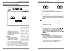
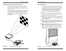
To connect the VTG 200 to a computer, refer to the picture
below and connect the user supplied RS-232 cable from the
computer (PC) serial port to the VTG 200 connector labeled
“RS-232”.
Page 5-1
VTG 200 RS-232 Control and Software
Pin # Function
2 Transmit Data (Tx)
3 Receive Data (Rx)
5 Signal Ground (Gnd)