


©2002 Fairchild Semiconductor Corporation Application Note 7502 Rev. A1
Turn-On
State 1: MOS Off, JFET Off
I
PK1
= V
G
/R
O
State 2: MOS Active, JFET Active
I
PK2
= (V
G
- V
GS(TH)
)/R
O
State 3: MOS Active, JFET Saturated
I
PK3
= (V
G
- V
G(SAT)
)/R
O
Turn-Off
State 4: MOS Saturated, JFET Saturated
I
PK4
= V
G
/R
O
State 5: MOS Active, JFET Saturated
I
PK5
= V
G(SAT)
/R
O
State 6: MOS Active, JFET Active
I
PK6
= V
G(SAT)
/R
O
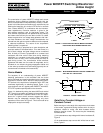
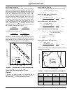
The equivalent circuit of Figure A-1 predicts that:
dV
D
/dt = (-g
M
R
L
(V
G
- V
GS(TH)
)e
-t/T1
) /T1
where T1 = R
O
C
GS
+ (1 + g
M
/g
MJ
)R
O
C
X
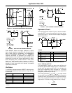
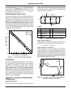
Note that g
M
R
L
(V
G
- V
GS(TH)
) is usually an order of magnitude
greater than V
DD
, indicating that the drain voltage is discharg-
ing toward a very large negative value. The device operation,
then, is on the early, almost linear, portion of the exponential,
where e
-t/T1
approximates unity. The drain current of Figure A-
2, and hence the drain voltage, does indeed exhibit a linear
decrease with time.
Thus, for state 2:
where I
PK2
= (V
G
- V
GS(TH)
)/R
O
State 3: Mos Active, JFET Saturated
Because of the Miller effect, the gate voltage and, hence, the
gate current, is almost constant during the tail time. The
equivalent circuit then predicts:
State 4: Mos Saturated, JFET Saturated (Turn-off)
Both equivalent-circuit generators are short circuits, and the
gate drive is discharging C
X
in parallel with C
GS
through R
O
.
t = R
O
(C
GS
+ C
X
) ln[V
G
/V
G(SAT)
]
I
PK4
= V
G
/R
O
State 5: Mos Active, JFET Saturated
The JFET current generator V
x
g
mJ
, is operative.
I
PK5
= V
G(SAT)
/R
O
State 6: Mos Active, JFET Active
The Miller effect is now reduced by the activation of V
G
g
MJ
,
and the equivalent circuit predicts:
I
PAK6
= V
G(SAT)
/R
O
Appendix B - Estimating R
O
for Some
Typical Gate-Drive Circuits
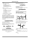
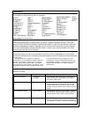
Case 1: Typical Pulse-Generator Drive, Figure B-1
FIGURE B-1. TYPICAL PULSE-GENERATOR DRIVE CIRCUIT
Turn-On and Turn-Off
R
O
= R
GEN
R
GS
/(R
GEN
+ R
GS
)
For the typical case where R
GEN
= 50Ω, and a coaxial-cable
termination of 50 ohms, R
O
= 25Ω and V
G
= V
GEN
/2.
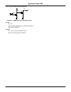
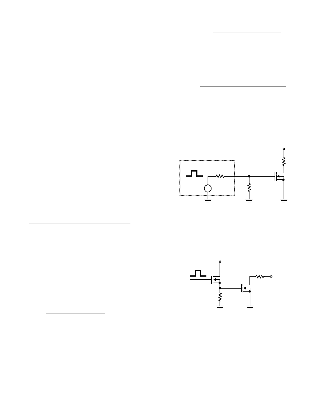
Case 2: Voltage-Follower Gate Drive, Figure B-2
FIGURE B-2. VOLTAGE-FOLLOWER GATE-DRIVE CIRCUIT
Turn-On
R
O
is approximately equal to 1/g
M
for R
S
very much
greater than 1/g
M
.
gm = transconductance of driving MOSFET transistor.
Turn Off
R
O
= R
S
t =
[V
DD
- V
DK
][C
GS
+ C
X
(1 + g
M
/g
MJ
)]
g
M
R
L
I
PK2
dV
D
=
g
M
R
L
l
G
=
l
G
dt C
GS
+ (1 + g
M
R
L
)C
X
C
X
l
G
= I
PK3
= (V
G
- V
G(SAT)
)/R
O
and t =
(V
DK
- V
D[SAT]
)C
x
I
PK3
t =
[V
DK
- V
D[SAT]
)C
X
I
PK5
t =
[V
DD
- V
DK
][C
GS
+ C
X
(1 + g
M
/g
MJ
)]
g
M
R
L
I
PAK6
V
GEN
R
GEN
V
G
V
DD
R
L
R
GS
+
R
S
V
DD
R
L
Application Note 7502