


© 2009 Fairchild Semiconductor Corporation www.fairchildsemi.com
FPF2300/02/03 • Rev. 1.1.3 11
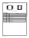
FPF2300/02/03 — Dual-Output Current Limit Switch
Description of Operation
The FPF2300, FPF2302, and FPF2303 are dual-output current-
limit switches designed to meet notebook computer, peripheral
USB port, and point-of-load (POL) application power requirements.
Dual-output current can be used where dual or quad USB ports are
powered by hosts or self-powered hubs. The FPF230X family
offers control and protection while providing optimum operation
current for a safe design practice. The core of each switch is a
typical 75mΩ (IN = 5.5V) P-channel MOSFET and a controller
capable of functioning over an input operating range of 1.8-5.5V.
The FPF230X family offers current limiting, UVLO (under-voltage
lockout), and thermal shutdown protection per each switch. In the
event of an over-current condition, the load switch limits the load to
current limit value. The minimum current limit is set to 1100mA.
On/Off Control
The ON pin is active LOW for FPF2300/2/3 and controls the state
of the switch. Pulling the ON pin continuous to LOW holds the
switch in the ON state. The switch moves into the OFF state when
the ON pin is pulled HIGH or if a fault is encountered. For all
versions, an under-voltage on input voltage or a junction
temperature in excess of 140°C overrides the ON control to turn off
the switch. In addition, excessive currents cause the switch to turn
off in the FPF2300 and FPF2302 after a 10ms blanking time. The
FPF2300 has an auto-restart feature that automatically turns the
switch ON again after 504ms. For the FPF2302, the ON pin must
be toggled to turn on the switch again. The FPF2303 does not turn
off in response to an over-current condition, but remains operating
in a constant-current mode as long as ON is enabled and the
thermal shutdown or UVLO is not activated. The ON pin does not
have a pull-down or pull-up resistor and should not be left floating.
Current Limiting
The current limit ensures that the current through the switch
doesn't exceed a maximum value, while not limiting at less than a
minimum value. FPF230X family has dual-output load switches
being housed in one package. The minimum current at which both
switches start limiting the load current is set to 1100mA. The
FPF2300 and FPF2302 have a blanking time of 10ms (typical),
during which the switch acts as a constant current source. At the
end of the blanking time, the switch is turned off. The FPF2303 has
no current limit blanking period, so it remains in a constant current
state until the ON pin of the affected switch is deactivated or the
thermal shutdown turns off the switch.
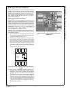
Fault Reporting
Over-current, input under-voltage, and over-temperature fault
conditions are signaled out by the FLAGB pin going LOW. A UVLO
fault is reported on both FLAGB(A) and FLAGB(B) simultaneously,
while over-current and over-temperature condition faults are
reported independently. FPF2300 and FPF2302 have a current
fault blanking feature that prevents over-current faults shorter than
the blanking time (t
BLANK(Typ)
= 10ms) from triggering the fault
signal (FLAGB) output.
If the over-current condition persists beyond the blanking time, the
FPF2300 pulls the FLAGB pin LOW and shuts the switch off. If the
ON pin is kept active, an auto-restart feature releases the FLAGB
pin and turns the switch on again after a 504ms auto-restart time
(t
RSTRT
). If the over-current condition persists beyond the blanking
time, the FPF2302 has a latch-off feature that pulls the FLAGB pin
LOW and shuts the switch off. The switch is kept off and the
FLAGB pin kept LOW until the ON pin is toggled. The FPF2303
responds to an overload condition by immediately pulling the
FLAGB pin LOW and the switch remains in constant current mode
until the output overload condition is removed. The FPF2303 has a
startup blanking feature that prevents current faults related to star-
tup transients from triggering the FLAGB output. The startup blank-
ing feature is effective for the first 10ms (typical) following device
turn-on via ON pin.
The FLAGB outputs are two open-drain MOSFETs that require a
pull-up resistor on each FLAGB pin. FLAGB can be pulled HIGH to
a voltage source other than input supply with maximum 5.5V. A
100KΩ pull-up resistor is recommended. When the ON pin is inac-
tive, the FLAGB is disabled to reduce current draw from the supply.
If the FLAGB is not used, the FLAGB can be connected to ground
on the PCB.
.
device wakeup
device wakeup
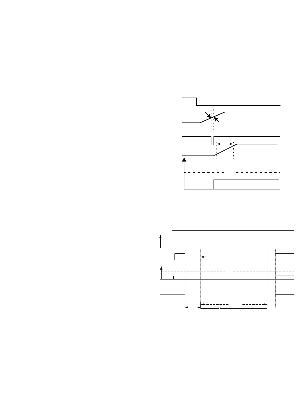
ON
IN
FLAGB
OUT
I
LOAD
I
LIMIT
10% V
OUT
90% V
OUT
RISE
TIME
VIN
ON
FLAGB
RL*
VOUT
tBLANK
ILOAD
ILIMIT
tRSTRT
Over
current
condtion
ILMIT
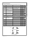
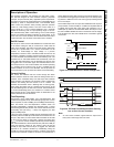
Figure 35. FLAGB Assertion in Under-Voltage Fault
Figure 36. FPF2300 FLAGB Reports While Entering
into an Over-Current Condition
Note:
6. An over-current condition signal loads the output with a
heavy load current larger than I
LIM
value.