


www.fairchildsemi.com 4
NC7SB3257
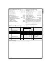
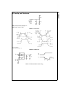
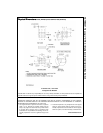
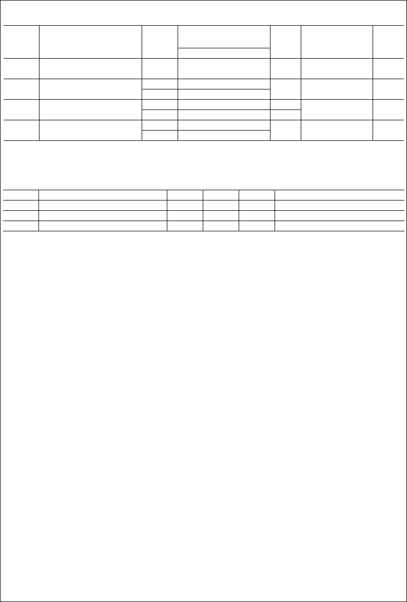
AC Electrical Characteristics
Note 6: This parameter is guaranteed by design but not tested. The bus switch contributes no propagation delay other than the RC delay of the On Resis-
tance of the switch and the 50 pF load capacitance, when driven by an ideal voltage source (zero output impedance).
Note 7: Guaranteed by design.
Capacitance (Note 8)
Note 8: Capacitance is characterized but not tested.
Symbol Parameter
T
A
= −40°C to +85°C
Units ConditionsV
CC
C
L
= 50 pF, RU = RD =500Ω
Figure
(V) Min Typ Max Number
t
PHL
Propagation Delay Bus to Bus 4.0 − 55 0.25
ns V
I
= OPEN
Figures
1, 2
t
PLH
(Note 6)
t
PZL
Output Enable Time 4.5 − 5.5 1.8 6.5
ns
V
I
= 7V for t
PZL Figures
1, 2
t
PZH
4.0 1.8 7.3 V
I
= 0V for t
PZH
t
PLZ
Output Disable Time 4.5 − 5.5 0.8 4.7 V
I
= 7V for t
PLZ Figures
1, 2
t
PHZ
4.0 0.8 5.3 V
I
= 0V for t
PHZ
t
B-M
Break Before Make Time 4.5 − 5.5 0.5
ns Figure 3
(Note 7) 4.0 0.5
Symbol Parameter Typ Max Units Conditions
C
IN
Control Pin Input Capacitance 2.3 pF V
CC
= 0V
C
IO-B
B Port OFF Capacitance 5.7 pF V
CC
= 5.0V
C
IO-A
A Port ON Capacitance 16 pF V
CC
= 5.0V