AN50 APPLICATION NOTE
18
Guidelines for Debugging and
Performance Evaluations
Debugging Your First Design Implementation
1. Note the setting of the VID pins to know what voltage is
to be expected.
2. Do not connect any load to the circuit. While monitoring
the output voltage, apply power to the part with current
limiting at the power supply. This ensures that no cata-
strophic shorts are present.
3. If proper voltage is not achieved go to "Procedures "
below.
4. When you have proper voltage, increase the current lim-
iting of the power supply to 16A.
5. Apply load at 1A increments. An active load (HP6060B
or equivalent) is suggested.
6. In case of poor regulation refer to "Procedures" below.
Procedures
1. If there is no voltage at the output and the circuit is not
drawing current look for openings in the connections,
check the circuitry versus schematic, and check the
power supply pins at the device to make sure that volt-
age(s) are applied.
2. If there is no voltage at the output and the circuit is
drawing excessive current (>100mA) with no load,
check for possible shorts. Determine the path of the
excessive current and which devise is drawing it—this
current may be drawn by peripheral components.
3. If the output voltage comes close to the expected value,
check the VID inputs at the device pins. The part is fac-
tory set to correspond to the VID inputs.
4. Premature shut down can be caused by an inappropriate
value of the sense resistor. See the “Sense Resistor” sec-
tion.
5. Poor load regulation can be due to many causes. Check
the voltages and signals at the critical pins.
6. The VREF pin should be at the voltage set by the VID
pins. If the power supply pins and the VID pins are
correct the VREF should have the correct voltage.
7. Next check the oscillator pin. You should see a saw tooth
wave at the frequency set by the external capacitor.
8. When the VREF and CEXT pins are checked and
correct and the output voltage is incorrect, look at the
waveform at VCCQP. This pin should be swinging from
ground to +12V (in the +12V application), and from
slightly below +5V to about +10V (charge pump appli-
cation). If the VCCQP pin is noisy, with ripples/over-
shoots riding on it this may make the converter not to
function correctly.
9. Next, look at HIDRV pin. This pin directly drives the
gate of the FET. It should provide a gate drive (Vgs) of
about 5V when turning the FET on. A careful study of
the layout is recommended. Refer to the “PCB Layout
Guidelines” section.
10. Past experience shows that the most frequent errors are
incorrect components, improper connections, and poor
layout.
Performance Evaluation
This section shows a sample evaluation results as a reference
guide for evaluating a DC-DC Converter using the RC5050
on a Pentium Pro motherboard.
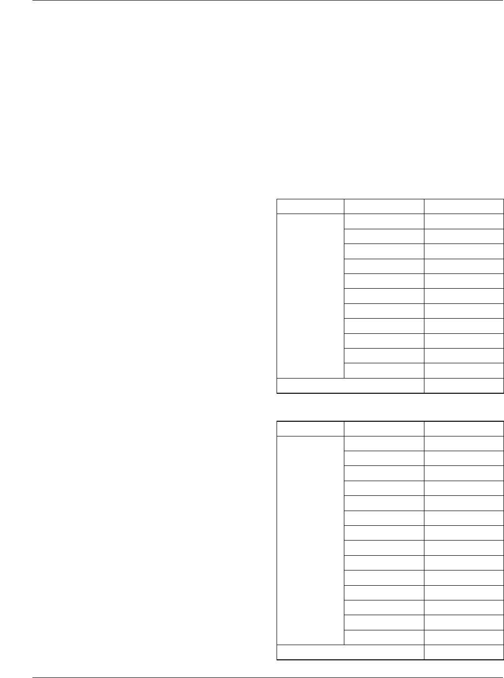
Load Regulation
VID I
load
(A) V
out
(V)
10100 0.5 3.0904
1.0 3.0825
2.0 3.0786
3.0 3.0730
4.0 3.0695
5.0 3.0693
6.0 3.0695
7.0 3.0695
8.0 3.0694
9.0 3.0694
9.9 3.0691
Load Regulation 0.5A – 9.9A 0.70%
VID I
load
(A) V
out
(V)
10010 0.5 3.2805
1.0 3.2741
2.0 3.2701
3.0 3.2642
4.0 3.2595
5.0 3.2597
6.0 3.2606
7.0 3.2611
8.0 3.2613
9.0 3.2611
10.0 3.2607
11.0 3.2599
12.0 3.2596
12.4 3.2596
Load Regulation 0.5A – 12.4A 0.64%


