


CHAPTER
CHAPTER
2
2
INSTALLATION INSTRUCTIONS
1. Verify the following is included in the UPS shipping carton:
(1) UPS, (1) Software Diskette(s) & Manual, (1) Power Cord (800VA-1KVA models only),
(1) Owners Manual & (1) UPS/Computer Cable.
2. Verify the UPS unit is configured for the proper input/output voltage and frequency. This
information is stated on the nameplate label located on the rear or the side panel of the
unit. If any special input plug and output receptacle configurations were specified at the
time of order, verify for proper configuration.
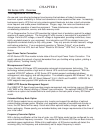
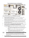
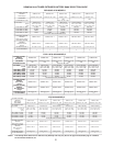
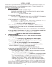
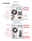
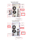
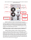
3. Set the dip switches located on the UPS rear panel for the nominal UPS output
voltage desired. See the dip switch setting tables located on page 6.
In most cases the nominal UPS output voltage should be set to match the incoming utility
voltage. This will assure a close matching voltage in the event the UPS is placed on
bypass. NOTE: Disregard the "ON" marking on the side of the actual dip switch
housing; use the tables in this manual or the silkscreen on the UPS rear panel only.
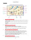
Dip switch 3 "enables" or "disables” the "Green Mode" function. The UPS is shipped
from the factory with the switch set in the "disabled" position (up). If SW3 is switched
down or to the "enabled" position, the Green Mode function is activated. When the
load connected to the output of the UPS drops to under 10% of the full rated UPS output
for 30 seconds, the UPS is automatically placed into bypass and the inverter is turned off.
NO BATTERY BACKUP IS PROVIDED AFTER THE GREEN MODE HAS ACTIVATED.
Dip switch settings must be made while the UPS is turned off. Any changes made while
the UPS is turned on will not take effect until the UPS is turn off and back on again since
the switch settings are read by the microprocessor only during initial UPS power up
.
4. To prevent accelerated battery discharge during shipment, the 1-3kVA models have had
the battery fuse removed. INSTALL THE BATTERY FUSE PRIOR TO TURNING ON THE
UPS INPUT CIRCUIT BREAKER OR PLUGGING IN THE UPS. Prior to installing the
battery fuse, depress the battery pre-charge button located on the UPS rear panel
for two seconds prior to inserting the battery fuse. Not applicable to 1kVA models.
NEVER REMOVE THE BATTERY FUSE WHILE THE UPS AC CIRCUIT BREAKER IS
TURNED ON AND OPERATING FROM THE UTILITY VOLTAGE OR UPS DAMAGE
MAY RESULT. THE UPS MUST BE COMPLETELY SHUT DOWN PRIOR TO DISABLING
THE INTERNAL BATTERY SUPPLY.
In the event this UPS is to be turned off or stored for more than four weeks, the battery
fuse must be removed to prevent excessive battery discharge. If placed in long-term
storage, every four months the UPS must be plugged in and turned on for 24 hours to
allow the batteries to recharge and prevent battery damage due to the normal battery
self-discharge asociated with sealed lead-acid batteries. Failure to follow these procedures
may cause battery damage and invalidate your warranty.
CAUTION
CAUTION
4