


FTLX1461E2 Product Specification – October 2008
© Finisar Corporation – October 2008 Rev B Page 3
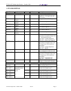
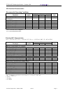
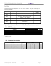
Receive Functions
Reserved
Reserved
O
O
38
39
Reserved For Future Use
Reserved For Future Use
RX LANE 0+
RX LANE 0–
O
O
41
42
Module XAUI Output Lane 0+
Module XAUI Output Lane 0–
RX LANE 1+
RX LANE 1–
O
O
44
45
Module XAUI Output Lane 1+
Module XAUI Output Lane 1–
RX LANE 2+
RX LANE 2–
O
O
47
48
Module XAUI Output Lane 2+
Module XAUI Output Lane 2–
RX LANE 3+
RX LANE 3–
AC-coupled,
Internally biased
differential
XAUI
O
O
50
51
Module XAUI Output Lane 3+
Module XAUI Output Lane 3–
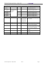
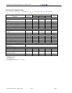
DC Power
GND 0 V DC 1, 2, 3, 33, 34,
35, 36, 37, 40,
43, 46, 49, 52,
53, 54, 57, 60,
63, 66, 69, 70
Ground connection for signal ground
on the module
APS +1.2 V 7, 8, 28, 29 Input from Adaptive Power Supply
APS SENSE +1.2 V 27 APS Sense Output. Connected to the
APS input inside transponder.
APS SET 25 Feedback input from APS.
Connected to GND through a 1180Ω
resistor inside the transponder.
3.3 V +3.3 V DC 5, 6, 30, 31 DC Power Input, +3.3 V DC,
Nominal
5.0 V +5.0 V DC 4, 32 DC Power Input, +5.0 V DC,
Nominal
Reserved 26 Reserved for APD.
Reserved 13 Reserved.