


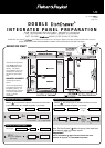
PANEL PREPARATION INSTRUCTIONS
4
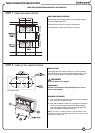
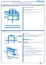
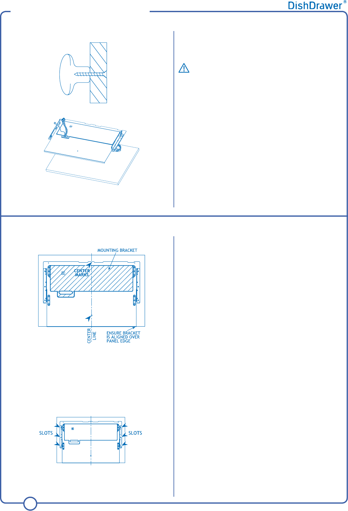
The Mounting Bracket is directly screwed to the back of the Integrated Panel.
On a soft surface centralize and align the Mounting Bracket on the Panel.
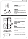
Important!
For some materials pilot holes may need to be drilled first before
screwing the Mounting Bracket onto the Panel. Be sure the drill does
not damage the face of the Panel.
Important!
The mounting bracket must not be modified in any way. It is designed
to hold the door front in the correct position to allow venting.
Important!
The door front must not extend beyond the bottom of the mounting
bracket. Drying problems and moisture damage may otherwise occur.
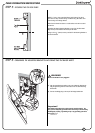
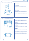
Using six
of the
5
/
8
” (16mm) screws supplied, secure the Mounting Bracket
to each Panel at the six points shown in the diagram.
NOTE: If the the six outermost slots are not able to be used to
securely fix the Mounting Brackets to the Panel, choose any
six well spaced slots about the Panel.
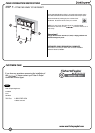
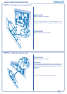
FITTING THE HANDLE
Fit the customer supplied handle.
WARNING!
When mounting the handle, be sure fastenings do not protrude
beyond the back surface of the Panel.
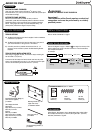
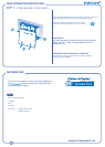
FITTING THE BADGE
Fit the Badge to the Panel by feeding the wires through to the back and
pressing the Badge into the cut out. If needed adhere the Badge to the
Panel with an adhesive.
Feed the Badge wires through the slot in the Mounting Bracket. As the
Mounting Bracket is placed on the rear of the Panel the excess wire must
be pulled through.
STEP 4: SECURING THE MOUNTING BRACKETS
STEP 3: FITTING THE HANDLE AND BADGE